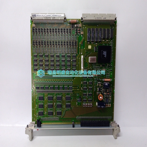
Home > Product > Gas turbine system > UR8CH Relay module
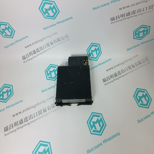
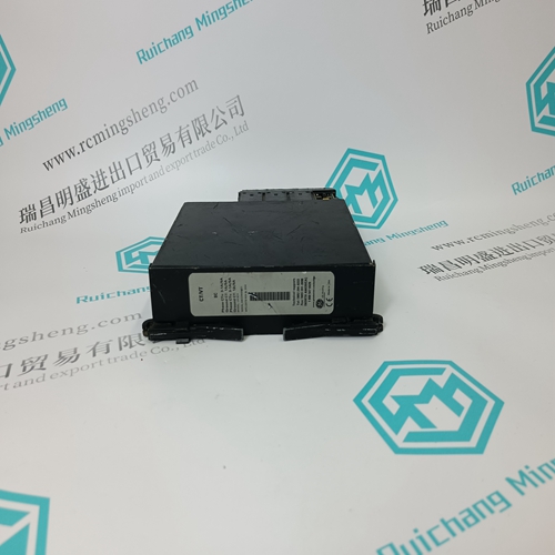
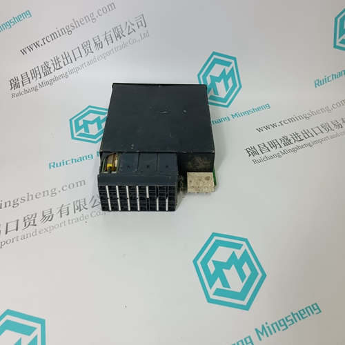
UR8CH Relay module
- Product ID: UR8CH
- Brand: GE
- Place of origin: the United States
- Goods status: new/used
- Delivery date: stock
- The quality assurance period: 365 days
- Phone/WhatsApp/WeChat:+86 15270269218
- Email:stodcdcs@gmail.com
- Tags:UR8CHRelay module
- Get the latest price:Click to consult
The main products
Spare parts spare parts, the DCS control system of PLC system and the robot system spare parts,
Brand advantage: Allen Bradley, BentlyNevada, ABB, Emerson Ovation, Honeywell DCS, Rockwell ICS Triplex, FOXBORO, Schneider PLC, GE Fanuc, Motorola, HIMA, TRICONEX, Prosoft etc. Various kinds of imported industrial parts
UR8CH Relay module
❑ Enabling switches may only be used if the operator activating the enabling switch recognizes the dangerous situation in time so that he can immediately take the necessary measures to avoid such situations! ❑ The enabling switch is only used to enable commands for performing dangerous movements. The commands themselves must be activated by a separate operating element (key on HT). Only persons who are allowed to activate the enabling switch are also allowed to work in the dangerous area. ❑ 2-position enabling switches may only be used in connection with an emergency stop facility. ❑ At the HT 40X, the enabling switches always feature 2 channels.
To be able to assess what rules or what parts of the rules are to be observed regarding the safety-related parts of a machine, the risk assessment can be carried out.
2.4 Risk Assessment of Machinery For the risk assessment the following standards must be applied: ❑ EN 292 „General principles for design of machinery“ ❑ EN 1050 „Principles for risk assessment of machinery“ ❑ EN 954-1 „Safety-related parts of control systems“
Functional procedure:
Only if both enabling switches ZT1 and ZT2 are activated „simultaneously“ both output relays K1 and K2 will energise and the output contacts 13-14 and 23-24 will close. The output relays K1 and K2 will not energise if • only one enabling switch is activated, • the simultaneity period is exceeded, • the feedback control loop X1-X2 is open. If an enabling switch is released after being simultaneously activated, the output relays K1 and K2 will de-energise again. The forced-guided output contacts 13-14 and 23-24 will open. The output relays will energise again only after both enabling switches have been released and simultaneously operated once again. In this way the enabling switches meet the requirement which consists in avoiding that one single error makes the safety function inoperational. A single error will be recognized at the next cycle at the latest.
The safety categories (B, 1, 2, 3, 4) which finally define the structure of safety-related parts of a machine result from this risk assessment. The following wiring diagram shows how the safety category 3 can be fulfilled with KEBA's handheld terminals and their safety-related parts. The entire concept of the machine must be laid out according to the principles of safety category 3.
