Home > Product > Servo control system > HIMA F7133 Output module
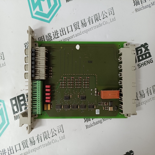
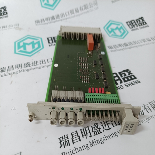
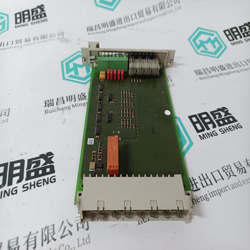
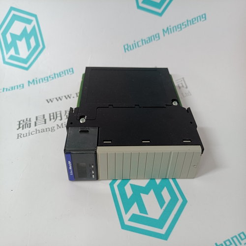
HIMA F7133 Output module
- Product ID: F7133
- Brand: HIMA
- Place of origin: the United States
- Goods status: new/used
- Delivery date: stock
- The quality assurance period: 365 days
- Phone/WhatsApp/WeChat:+86 15270269218
- Email:stodcdcs@gmail.com
- Tags:HIMAF7133Output module
- Get the latest price:Click to consult
The main products
Spare parts spare parts, the DCS control system of PLC system and the robot system spare parts,
Brand advantage: Allen Bradley, BentlyNevada, ABB, Emerson Ovation, Honeywell DCS, Rockwell ICS Triplex, FOXBORO, Schneider PLC, GE Fanuc, Motorola, HIMA, TRICONEX, Prosoft etc. Various kinds of imported industrial parts
Products are widely used in metallurgy, petroleum, glass, aluminum manufacturing, petrochemical industry, coal mine, papermaking, printing, textile printing and dyeing, machinery, electronics, automobile manufacturing, tobacco, plastics machinery, electric power, water conservancy, water treatment/environmental protection, municipal engineering, boiler heating, energy, power transmission and distribution and so on.
HIMA F7133 Output module
The INICT12 Computer Transfer Module handles all communication with a host computer. The module is a single printed circuit board that occupies one slot in a module mounting unit. The circuit board contains communication circuitry that enables it to directly communicate with its INNIS01 module over a dedicated I/O expander bus. Two latching screws on the faceplate secure the INICT12 module to the module mounting unit (Fig. 2-4). There are nine LEDs on the faceplate and a stop/reset pushbutton. The INICT12 module has three card edge connectors for external signals and power (P1, P2, and P3). Connector P1 connects to common, +5 VDC power. Connector P2 connects the INICT12 module to the I/O expander bus to communicate with its INNIS01 module. P3 connects the module to its NTMP01 Multifunction Processor termination unit.
The INICT12 module supports RS-232-C protocol for computer interface. An NTMP01 termination unit provides two RS-232-C ports: port zero (P5) is normally for computer connection and port one (P6) is normally for diagnostic terminal or security key connection. Diagnostic port or security key capability must first be enabled for the INICT12 module (SW4). Control and data signals connect to the INICT12 module through a NKTU01 or NKTU11 cable attached between its P3 connector and P1 of the NTMP01 termination unit. When communicating through the RS-232-C ports, the INICT12 module can support either data terminal equipment (DTE) or data communication equipment (DCE). The NTMP01 unit has jumpers to configure DTE or DCE operation. The termination unit provides optical isolation for the RS-232-C ports.
Block Diagram
Figure 2-5 is a functional block diagram of the INICT12 module. The module primarily contains a central processing unit (CPU), memory, and I/O expander bus and RS-232-C serial channel interfaces. Refer to I/O Expander Bus previously in this section for an explanation of the I/O expander bus interface. CPU The CPU contains a 32-bit microprocessor running at 16 megahertz and associated support circuitry (i.e., control logic, address decoder, interrupt interface, system timer, etc.). The CPU interprets and executes instructions to perform its computer interface functions, control communication, and run diagnostics. Since the microprocessor is responsible for overall module operation, it communicates with all the functional blocks. Memory The INICT12 module memory consists of ROM memory, SRAM memory, and nonvolatile-RAM (NVRAM) memory. The ROM memory holds the operating system instructions for the microprocessor (i.e., firmware). The SRAM memory provides temporary storage and a copy of the point definition database. The NVRAM memory holds the point definition database. The information stored in NVRAM is retained when power is lost. RS-232-C Serial Channels The INICT12 module contains two independent RS-232-C serial channels (A and B). These channels are connected to port zero and port one of the NTMP01 termination unit. The module uses a dual universal asynchronous receiver/transmitter (DUART) circuit to direct data transfer through the serial channels. Each channel supports standard baud rates up to 19.2 kilobaud.
