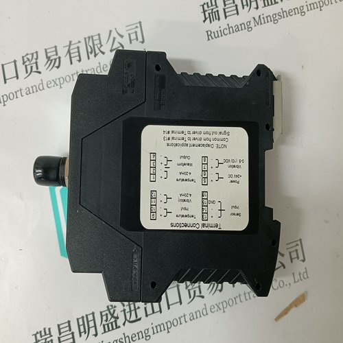
Home > Product > PLC programmable module > ICS TRIPLEX T9310-02 terminal
ICS TRIPLEX T9310-02 terminal
- Product ID: T9310-02
- Brand: ICS TRIPLEX
- Place of origin: the United States
- Goods status: new/used
- Delivery date: stock
- The quality assurance period: 365 days
- Phone/WhatsApp/WeChat:+86 15270269218
- Email:stodcdcs@gmail.com
- Tags:ICS TRIPLEXT9310-02terminal
- Get the latest price:Click to consult
The main products
Spare parts spare parts, the DCS control system of PLC system and the robot system spare parts,
Brand advantage: Allen Bradley, BentlyNevada, ABB, Emerson Ovation, Honeywell DCS, Rockwell ICS Triplex, FOXBORO, Schneider PLC, GE Fanuc, Motorola, HIMA, TRICONEX, Prosoft etc. Various kinds of imported industrial parts
Products are widely used in metallurgy, petroleum, glass, aluminum manufacturing, petrochemical industry, coal mine, papermaking, printing, textile printing and dyeing, machinery, electronics, automobile manufacturing, tobacco, plastics machinery, electric power, water conservancy, water treatment/environmental protection, municipal engineering, boiler heating, energy, power transmission and distribution and so on.
ICS TRIPLEX T9310-02 terminal
This procedure explains how to clean the printed circuit boards (i.e., module and termination unit boards). Parts None. Tools • Clean, dry, filtered compressed air. • Antistatic vacuum. • Isopropyl alcohol (99.5 percent electronic grade). • Foam-tipped swab. • Distilled water. • Nonabrasive eraser. • Fiberglass or nylon burnishing brush. • Piece of scrap printed circuit board. • Soft lint-free cloths. There are several cleaning procedures described. Use the procedures that meet the needs of the particular printed circuit board to remove all dust, dirt, oil, corrosion, or any other contaminants from the board. Perform all cleaning and handling of the printed circuit boards at static safe workstations. Always observe electrostatic sensitive device handling precautions when handling printed circuit boards.
When checking connections, always turn a screw, nut, or other fastening device in the direction to tighten only. If the connection is loose, it will be tightened. If the connection is tight, the tightening action will verify that it is secure. There should not be any motion done to loosen the connection.
Display Mode
Test Number The test number display mode uses LEDs one through six to display the diagnostic test number and LED eight to display whether the test passed or failed (Fig. PR16-1). If a diagnostic test is successful, LEDs one through six display the diagnostic test number and LED eight does not illuminate. If a diagnostic test is not successful, LEDs one through six still display the diagnostic test number but LED eight will illuminate. LED seven is not used in test number display mode.t The pass/fail display mode uses LEDs one through eight to display a combination of incrementing pass and fail counters (Fig. PR16-1). LEDs one through four display a binary count of the number of passed tests and LEDs five through eight display the number of failed tests. Halt On Error Disabled If halt on error is disabled, the selected test runs repeatedly until the module is removed. Depending on the display mode, the status indicators will identify the test being run or will display a test count (Fig. PR16-1). Enabled If halt on error is enabled, the test stops if an error is encountered. Depending on the display mode, the status indicators will identify the test that failed or will display a test count. The test continues to run, however, if no error is detected.
