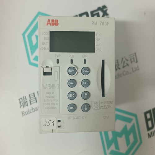
Home > Product > Robot control system > PHILIPS 958481321300 350211080380 module
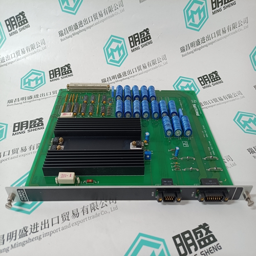
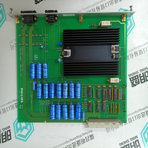
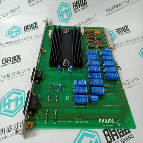
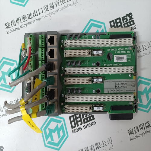
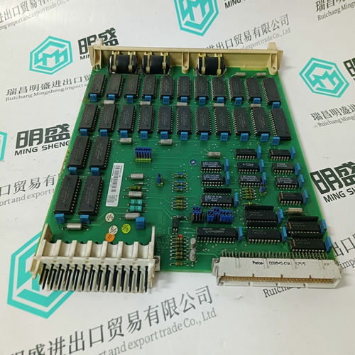
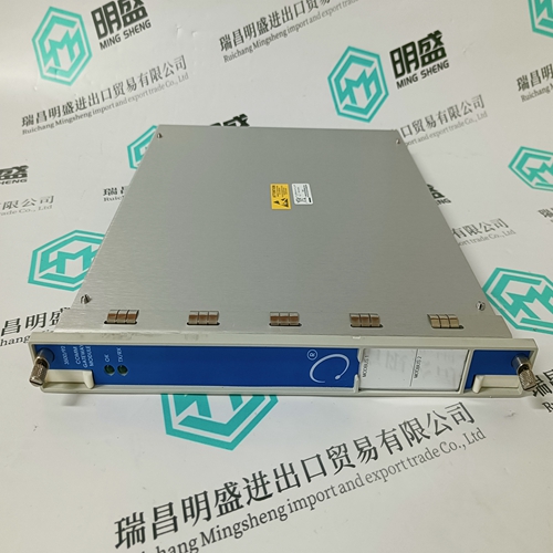
PHILIPS 958481321300 350211080380 module
- Product ID: 958481321300 350211080380
- Brand: PHILIPS
- Place of origin: the United States
- Goods status: new/used
- Delivery date: stock
- The quality assurance period: 365 days
- Phone/WhatsApp/WeChat:+86 15270269218
- Email:stodcdcs@gmail.com
- Tags:PHILIPS958481321300 350211080380module
- Get the latest price:Click to consult
The main products
Spare parts spare parts, the DCS control system of PLC system and the robot system spare parts,
Brand advantage: Allen Bradley, BentlyNevada, ABB, Emerson Ovation, Honeywell DCS, Rockwell ICS Triplex, FOXBORO, Schneider PLC, GE Fanuc, Motorola, HIMA, TRICONEX, Prosoft etc. Various kinds of imported industrial parts
Products are widely used in metallurgy, petroleum, glass, aluminum manufacturing, petrochemical industry, coal mine, papermaking, printing, textile printing and dyeing, machinery, electronics, automobile manufacturing, tobacco, plastics machinery, electric power, water conservancy, water treatment/environmental protection, municipal engineering, boiler heating, energy, power transmission and distribution and so on.
PHILIPS 958481321300 350211080380 module
To provide protection in a fault (output overload) condition, the unit is equipped with internal current-limiting circuitry and can endure current limiting for an unlimited duration. At the point of current-limit inception, the unit shifts from voltage control to current control. If the output voltage is pulled very low during a severe fault, the current-limit circuit can exhibit either foldback or tailout characteristics (output-current decrease or increase). The unit operates normally once the output current is brought back into its specified range.To turn the power module on and off, the user must supply a switch to control the voltage between the on/off terminal and the VI(–) terminal (Von/off). The switch can be an open collector or equivalent (see Figure 16). A logic low is Von/off = –0.7 V to 1.2 V, during which the module is off. The maximum Ion/off during a logic low is 1 mA. The switch should maintain a logiclow voltage while sinking 1 mA. During a logic high, the maximum Von/off generated by the power module is 6 V. The maximum allowable leakage current of the switch at Von/off = 6 V is 50 µA. The module has internal capacitance to reduce noise at the ON/OFF pin. Additional capacitance is not generally needed and may degrade the start-up characteristics of the module.
Remote Sense
Remote sense minimizes the effects of distribution losses by regulating the voltage at the remote-sense connections. The voltage between the remote-sense pins and the output terminals must not exceed the output voltage sense range given in the Feature Specifications table, for example, for the CC030Bs: [VO(+) – VO(–)] – [SENSE(+) – SENSE(–)] ð 0.5 V The voltage between the VO(+) and VO(–) terminals must not exceed 13.2 V. This limit includes any increase in voltage due to remote-sense compensation, set-point adjustment, and trim (see Figure 17).Output voltage adjustment allows the user to increase or decrease the output voltage set point of a module. This is accomplished by connecting an external resistor between the TRIM pin and either the SENSE(+) or SENSE(–) pins (see Figures 18 and 19). With an external resistor between the TRIM and SENSE(–) pins (Radj-up), the output voltage set point (VO, adj) increases.
The combination of the output voltage adjustment range and the output voltage sense range given in the Feature Specifications table cannot exceed 110% of the nominal output voltage between the Vo(+) and Vo(–) terminals.
