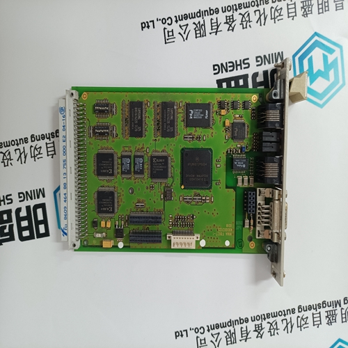
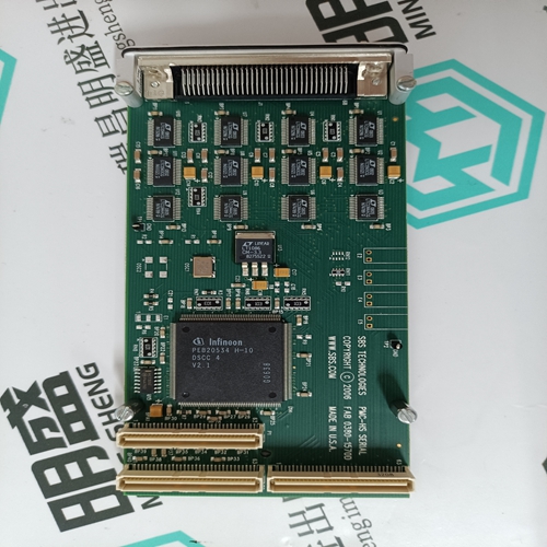
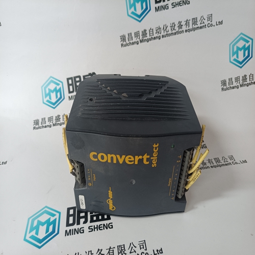
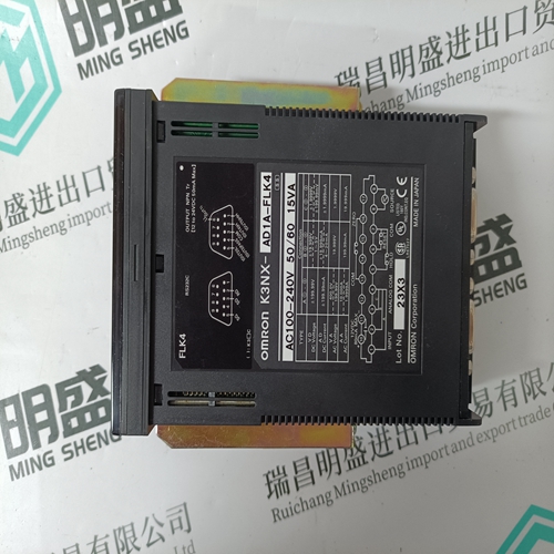
Home > Product > Robot control system > PROCESSOR 958481320201 350211080460 module
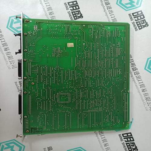
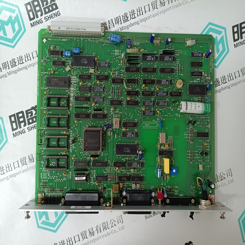
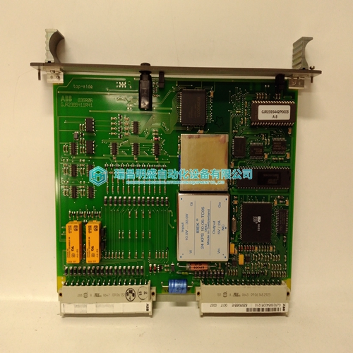
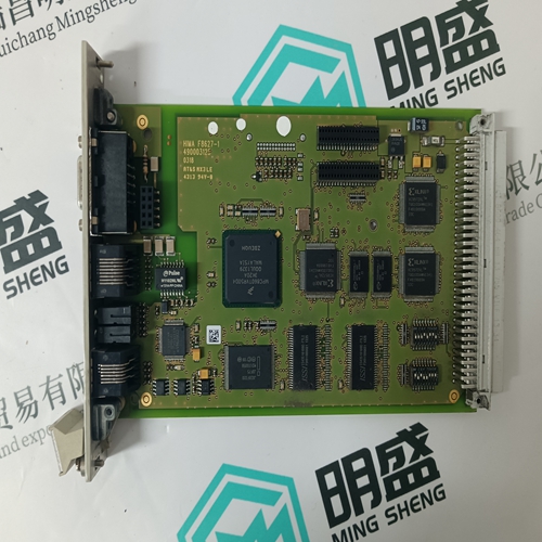
PROCESSOR 958481320201 350211080460 module
- Product ID: 958481320201 350211080460
- Brand: PPROCESSOR
- Place of origin: the United States
- Goods status: new/used
- Delivery date: stock
- The quality assurance period: 365 days
- Phone/WhatsApp/WeChat:+86 15270269218
- Email:stodcdcs@gmail.com
- Tags:PROCESSOR958481320201 350211080460module
- Get the latest price:Click to consult
The main products
Spare parts spare parts, the DCS control system of PLC system and the robot system spare parts,
Brand advantage: Allen Bradley, BentlyNevada, ABB, Emerson Ovation, Honeywell DCS, Rockwell ICS Triplex, FOXBORO, Schneider PLC, GE Fanuc, Motorola, HIMA, TRICONEX, Prosoft etc. Various kinds of imported industrial parts
Products are widely used in metallurgy, petroleum, glass, aluminum manufacturing, petrochemical industry, coal mine, papermaking, printing, textile printing and dyeing, machinery, electronics, automobile manufacturing, tobacco, plastics machinery, electric power, water conservancy, water treatment/environmental protection, municipal engineering, boiler heating, energy, power transmission and distribution and so on.
PROCESSOR 958481320201 350211080460 module
To determine the necessary airflow, determine the power dissipated by the unit for the particular application. Figures 21 through 23 show typical power dissipation for these power modules over a range of output currents. With the known power dissipation and a given local ambient temperature, the appropriate airflow can be chosen from the derating curves in Figure 24. For example, if the unit dissipates 6.2 W, the minimum airflow in a 80 °C environment is 1.0 ms–1 (200 ft./min).
Several heat sinks are available for these modules. The case includes through threaded mounting holes allowing attachment of heat sinks or cold plates from either side of the module. The mounting torque must not exceed 0.56 N-m (5 in.-lb). Figure 25 shows the case-to-ambient thermal resistance, θ (°C/W), for these modules. These curves can be used to predict which heat sink will be needed for a particular environment. For example, if the unit dissipates 7.1 W of heat in an 80 °C environment with an airflow of 0.5 ms–1 (100 ft./min.), the minimum heat sink required can be determined as follows: θ ≤ ( ) TC max , – TA ⁄ PD where: θ = module's total thermal resistance Tc, max = case temperature (See Figure 20.) TA = inlet ambient temperature (See Figure 20.) PD = power dissipation θ ð (100 – 80)/7.1 θ ð 2.8 °C/W From Figure 25, the 1/2 in. high heat sink or greater is required.
Layout Considerations
Copper paths must not be routed beneath the power module standoffs. Although the previous example uses 100 °C as the maximum case temperature, for extremely high-reliability applications, one can use a lower temperature for Tc, max. It is important to point out that the thermal resistances shown in Figure 25 are for heat transfer from the sides and bottom of the module as well as the top side with the attached heat sink; therefore, the case-to-ambient thermal resistances shown will generally be lower than the resistance of the heat sink by itself. The data in Figure 25 was taken with a thermally conductive dry pad between the case and the heat sink to minimize contact resistance (typically 0.1 °C/W to 0.3 °C/W). For a more detailed explanation of thermal energy management for this series of power modules as well as more details on available heat sinks, please request the following technical note: Thermal Energy Management CC-, CW-, DC-, and DW-Series 25 W to 30 W Board-Mounted Power Modules (TN97-015EPS).
