Home > Product > Gas turbine system > GE IS2020LNPSG3A Logic control module
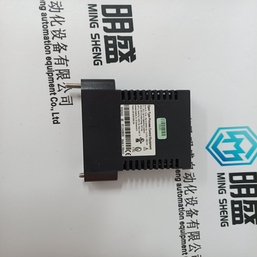
GE IS2020LNPSG3A Logic control module
- Product ID: IS2020LNPSG3A
- Brand: GE
- Place of origin: The United States
- Goods status: new/used
- Delivery date: stock
- The quality assurance period: 365 days
- Phone/WhatsApp/WeChat:+86 15270269218
- Email:stodcdcs@gmail.com
- Tags:GEIS2020LNPSG3ALogic control module
- Get the latest price:Click to consult
GE IS2020LNPSG3A Logic control module
This chapter describes setting parameters associated with the velocity and position loops. In some cases the user must adjust control loop parameters due to large mismatches between motor and load inertia, mechanical resonance, backlash, etc. This chapter provides guidance for handling these situations. Refer to Appendix A Selecting Motor Control Functionality for a description of the control loop architecture and control loop block diagrams. NOTE The two anti-resonant zeroes (ARZ0 and ARZ1) are assumed to both be off (set to zero) for this discussion.
VELOCITY LOOP
The velocity loop block diagram is shown in Figure 2 in Appendix A. Velocity loop bandwidth is the key indicator of system performance. Systems with fast settling time must have high velocity loop bandwidth. Conversely, if the velocity loop bandwidth is low, attempting to achieve fast settling time by increasing the position loop bandwidth, KPP, leads to overshoot and ringing.

![]()
Brand display
ABB、GE/FUANC、FOXBORO、TRICONEX 、BENTLY、A-B、EMERSON 、MOTOROLA、XYVOM、HONEYWELL 、REXROTH、KUKA、NI、DEIF、Yokogawa、WOODWARD、Reliance Electric、SCHNEIDER 、MOOG、PROSOFT、KOLLMORGEN、ICS TRIPLEX、HIMA
This article from the temporal Ming sheng automation equipment co., LTD., reproduced please attach this link: http://www.stockdcs.com/