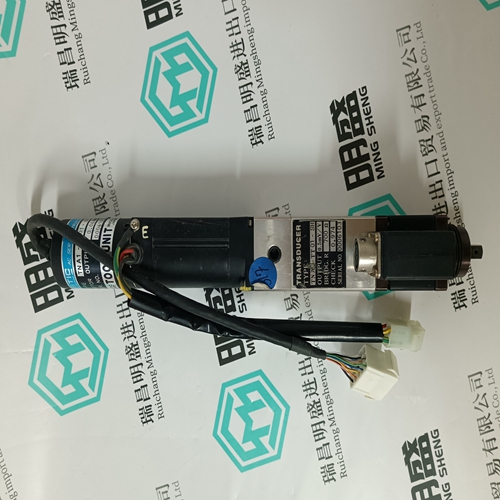
Home > Product > PLC programmable module > 6186-M15ALTR/B Operation panel
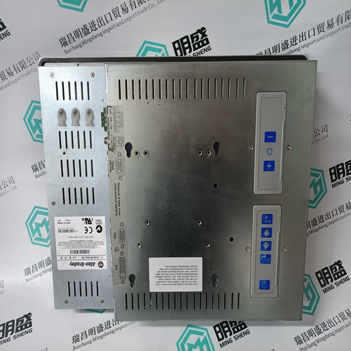
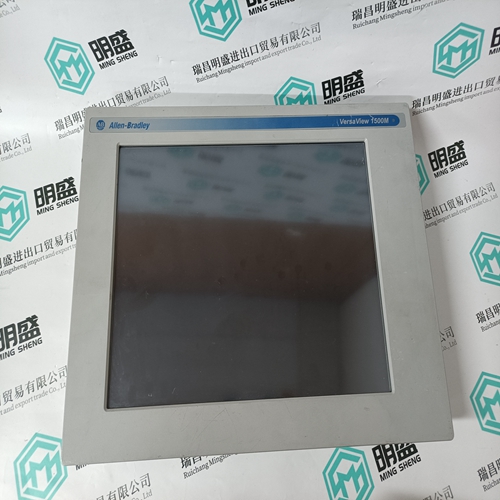
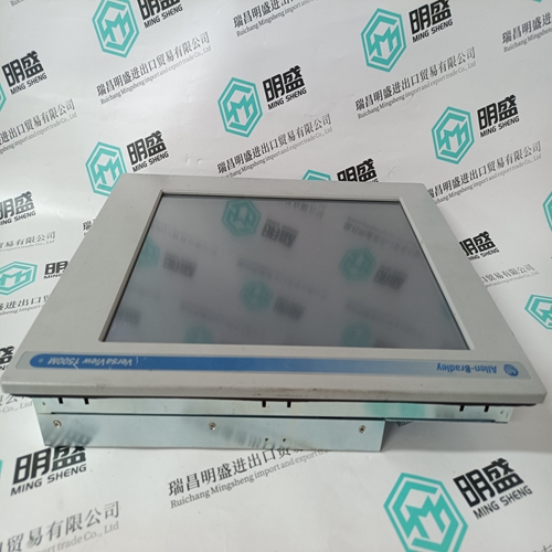
6186-M15ALTR/B Operation panel
- Product ID: 6186-M15ALTR/B
- Brand: A-B
- Place of origin: the United States
- Goods status: new/used
- Delivery date: stock
- The quality assurance period: 365 days
- Phone/WhatsApp/WeChat:+86 15270269218
- Email:stodcdcs@gmail.com
- Tags:6186-M15ALTR/BOperation panel
- Get the latest price:Click to consult
The main products
Spare parts spare parts, the DCS control system of PLC system and the robot system spare parts,
Brand advantage: Allen Bradley, BentlyNevada, ABB, Emerson Ovation, Honeywell DCS, Rockwell ICS Triplex, FOXBORO, Schneider PLC, GE Fanuc, Motorola, HIMA, TRICONEX, Prosoft etc. Various kinds of imported industrial parts
Products are widely used in metallurgy, petroleum, glass, aluminum manufacturing, petrochemical industry, coal mine, papermaking, printing, textile printing and dyeing, machinery, electronics, automobile manufacturing, tobacco, plastics machinery, electric power, water conservancy, water treatment/environmental protection, municipal engineering, boiler heating, energy, power transmission and distribution and so on.
6186-M15ALTR/B Operation panel
Multiple Drives/Nodes Connect an Ethernet communications cable from the XMP-SynqNet controller's OUT port to the SynqNet IN port (J11) of the first drive/node. Connect an Ethernet cable from the node's SynqNet OUT port (J12) to the SynqNet IN port (J11) of the next node. Connect another cable from the SynqNet OUT port (J12) of the last node in the topology to the SynqNet IN port of the XMP-SynqNet controller.If you do not know which type of drive is connected, click the Test button. The returned message will either say that there is no connection, confirm that you have an S200 connected, or tell you that the connected node is NOT an S200 drive.The installed S200 drive(s) will now be listed as "Online" and will list its configuration and status options. If there are additional S200 nodes on the network, they are automatically discovered. When using a network with multiple SynqNet nodes, use the SynqNet controller/node pulldown bars to select a particular node on the network to display in the Online mode.NOTE for SynqNet: Although the S200 Tools software maintains communication with all properly connected S200 drives drives on the SynqNet network, only one SynqNet node will be displayed at a time under the Online display. 4.2.5 SynqNet Configuration The next step is to set the proper drive and motor feedback configurations. Under the SynqNet Options tab, select the source for motor feedback (Feedback Source). Select Base Unit Feedback if the motor feedback is connected to J3 on the S200 Drive. Select Option Card Feedback if the motor feedback is connected to J14 on the S200 Drive.
Save Options
There are three types of Save options. It is important to know how to use each type to ensure that configurations are not lost. • Download NV - This button will save the parameter settings displayed in S200 Tools to the selected drive. These parameters are saved to the drive's permanent memory and are recalled during a power-up cycle. • Download Drive - This button will save the parameter settings displayed in S200 Tools to the selected drive/node. However, unlike Download NV, these parameters are only saved to the drive's temporary RAM and will not be recalled at a power-up cycle. It is recommended that you use the Download Drive button when testing settings. Once you are satisfied with the settings, click the Download NV button to permanently save the settings to the drive. • Save/Save As - You can also save the settings of a drive as a configuration file (*.S2C). Remember, saving a configuration file does NOT save the settings to the drive. Configuration files can be helpful for saving multiple drive setups. You can easily download a setting to a drive by opening the configuration file in the Offline mode and clicking the Download NV/Drive buttons once the proper drive is selected in the Online mode. It is recommended that you save a configuration file for each setup.
MOUNTING THE DRIVE The S200 drives are designed for operation in a cabinet using the following installation instructions: Mount the drives vertically inside a cabinet on a flat, solid, electrically conductive mounting surface that is connected to PE (Protective Earth Ground) and capable of supporting the weight of the unit. Provide a good connection to PE. Remove the paint on the mounting surface over an area extending at least 12 mm (0.5 in) from the mounting bolts to achieve good electrical connection over a large area between the drive and grounded mounting surface. Ensure that the environment within the cabinet meets the requirements listed in the Specifications.
