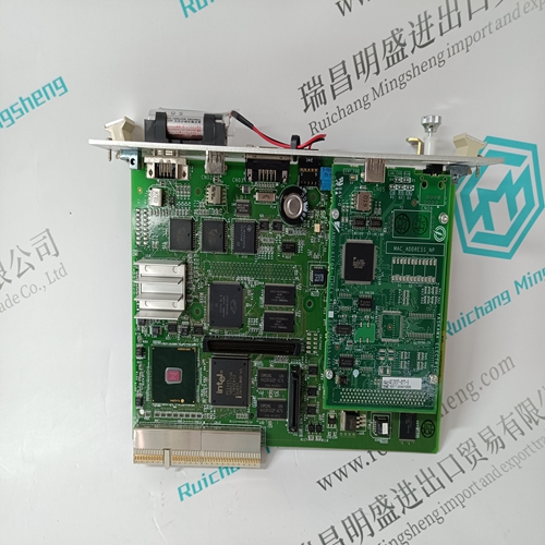
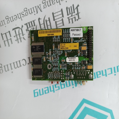
Home > Product > Gas turbine system > IC695CPE310-ABAD gas turbine electric card
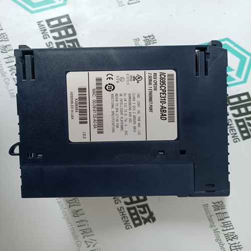
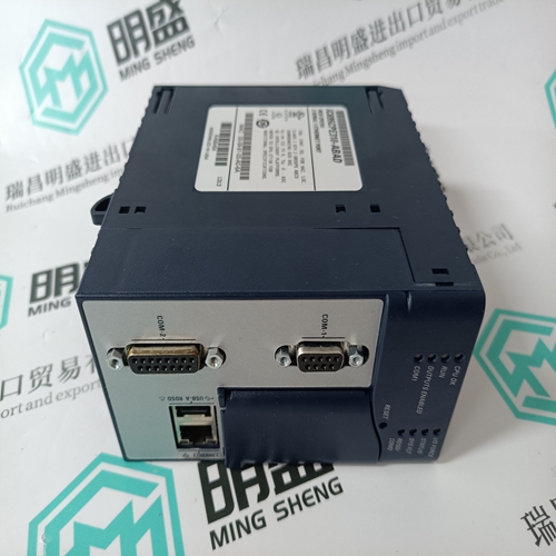
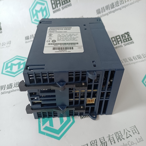
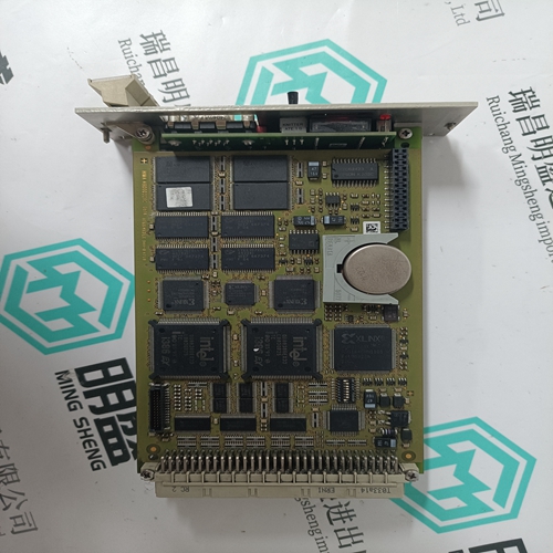
IC695CPE310-ABAD gas turbine electric card
- Product ID: IC695CPE310-ABAD
- Brand: GE
- Place of origin: the United States
- Goods status: new/used
- Delivery date: stock
- The quality assurance period: 365 days
- Phone/WhatsApp/WeChat:+86 15270269218
- Email:stodcdcs@gmail.com
- Tags:IC695CPE310-ABADgas turbine electric card
- Get the latest price:Click to consult
The main products
Spare parts spare parts, the DCS control system of PLC system and the robot system spare parts,
Brand advantage: Allen Bradley, BentlyNevada, ABB, Emerson Ovation, Honeywell DCS, Rockwell ICS Triplex, FOXBORO, Schneider PLC, GE Fanuc, Motorola, HIMA, TRICONEX, Prosoft etc. Various kinds of imported industrial parts
Products are widely used in metallurgy, petroleum, glass, aluminum manufacturing, petrochemical industry, coal mine, papermaking, printing, textile printing and dyeing, machinery, electronics, automobile manufacturing, tobacco, plastics machinery, electric power, water conservancy, water treatment/environmental protection, municipal engineering, boiler heating, energy, power transmission and distribution and so on.
IC695CPE310-ABAD gas turbine electric card
The -BUS terminal is usually left open during normal operation. In special multi-axis applications, drive buses can be wired in parallel to allow returned energy from one motor to power another and limit high regen powers. J1-4 or TB1-7 +BUS The +BUS terminal is used with the J1-2, REGEN, terminal to add a regen resistor to the drive to absorb regenerated energy. J1-5, J1-6 or J1-2, J1-3 C2 CTRL VAC C1 CTRL VAC These terminals connect 120/240 VAC power to the drive’s control voltage power supply. S21260, S2460 on separate 3 pin pluggable J1. These terminals are NOT connected to the bus power L1, L2 (J1-8,9) inside the drive
Control power input. The DC drive accepts +10 to +90 VDC on this input referenced to J1-2. An isolated regulated or isolated unregulated power supply can be used. This input can be connected to +Bus input (J1-3) and powered by the same supply as +Bus. The control power supply should be rated for 20 watts. While the power drain typically is 2 W to 8 W, a 20 W supply ensures reliable starting of the drive. J1-2 BUS/CTRL GND Power return for the control and BUS power supplies. The BUS/CTRL GND is connected to I/O RTN internally in the drive. J1-3 +BUS Main power input to the drive. The DC drive accepts +20 to +90 VDC on this input referenced to J1-2. An isolated regulated or isolated unregulated power supply can be used. The +Bus power drain with +Bus voltage at 75 VDC is in the range shown below. It varies according to the application and motor.
Bus Voltage
Bus voltage outside the operating range (20 to 90 V) causes an undervoltage or overvoltage fault. Undervoltage and overvoltage faults are self-cleared when the fault conditions are cleared. NOTE Do Not allow the Bus Voltage to exceed + 90 VDC as it can damage the drive. Target design center voltage for unregulated supply is +70 to +75 VDC. This provides 15 to 20 VDC margin for line tolerance, transformer regulation, and regen pump up. Design center voltage for a regulated supply can be up to +80 VDC. 6.4.3 Control Voltage The control voltage range for normal operation is +10 VDC to +90 VDC. The control voltage can either be wired to the bus voltage so one supply can power the drive, or from a separate supply. Separately powering the control from the bus allows the bus to be powered down for safety while drive status and fault information remain available. NOTE: Control and I/O can share a single +10 VDC to +30 VDC power supply. NOTE Do NOT allow the Control Voltage to exceed + 90 VDC as it can damage the drive.
