Home > Product > PLC programmable module > MVME7100 Digital card
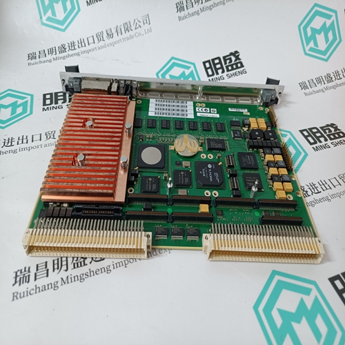
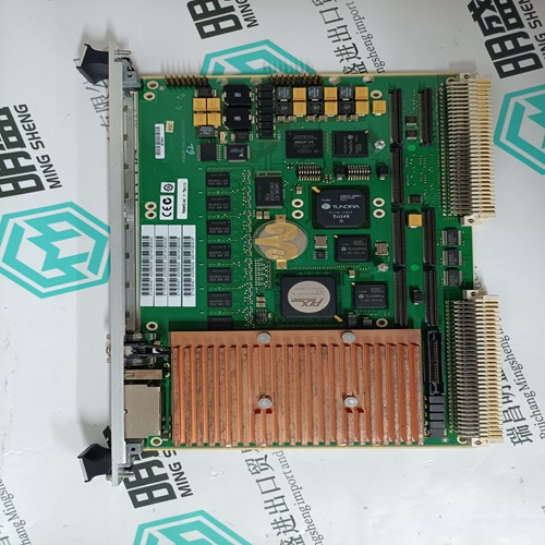
MVME7100 Digital card
- Product ID: MVME7100
- Brand: MOTOROLA
- Place of origin: the United States
- Goods status: new/used
- Delivery date: stock
- The quality assurance period: 365 days
- Phone/WhatsApp/WeChat:+86 15270269218
- Email:stodcdcs@gmail.com
- Tags:MVME7100Digital card
- Get the latest price:Click to consult
The main products
Spare parts spare parts, the DCS control system of PLC system and the robot system spare parts,
Brand advantage: Allen Bradley, BentlyNevada, ABB, Emerson Ovation, Honeywell DCS, Rockwell ICS Triplex, FOXBORO, Schneider PLC, GE Fanuc, Motorola, HIMA, TRICONEX, Prosoft etc. Various kinds of imported industrial parts
Products are widely used in metallurgy, petroleum, glass, aluminum manufacturing, petrochemical industry, coal mine, papermaking, printing, textile printing and dyeing, machinery, electronics, automobile manufacturing, tobacco, plastics machinery, electric power, water conservancy, water treatment/environmental protection, municipal engineering, boiler heating, energy, power transmission and distribution and so on.
MVME7100 Digital card
Grounding Provide safety isolation with the external bus and control supplies from the power line. NOTE The drive cannot be powered from an electrically Hot supply as it does not contain an isolation barrier. The Ctrl and Bus voltages and non-opto coupled I/O grounds (I/O RTN) are commoned inside the drive. The Ctrl and Bus power supplies share a ground pin (Bus/Ctrl Gnd). Join and connect to the negative terminals of the Ctrl and Bus power supplies. The I/O RTNs are normally connected to the signal ground of the system. (Some of the I/O is opto coupled and have separate returns. Be sure to thoroughly review this document for details.) The power supply negative terminal should be grounded somewhere in the cabinet. The chassis should also be grounded. In normal operation there should be no significant voltage between ground and the Bus/Ctrl Gnd and I/O RTNs. NOTE The maximum voltage allowed between Bus/Ctrl Gnd and chassis is 100 VDC.There is a minimum requirement on the output capacitance of the bus power supply for the S200 DC Input Drives. This capacitor is needed to absorb energy during motor deceleration and motor disable. It also helps provide energy during motor acceleration. For multiple S200 drives operated from one supply, the recommendation is to increase the capacitance according to the number of drives. For example, for four 6 A / 18 ARMS DC S200 drives powered from one 75 VDC supply, the recommended minimum bus output capacitance of the supply is 4 x 4,000 µf = 16,000 µf. Bus capacitor voltage rating should be 100 V. Bus capacitor type is aluminum electrolytic.
Bus Switching and Fusing
Do NOT put E-Stop switches or contactors between the drive bus pin (J1-3) and the power supply bus capacitor. There is a risk of damage to the drive if the bus is disconnected from the power supply capacitor when the drive is enabled. The motor does not need to be rotating to regenerate energy. The motor windings store magnetic energy that regenerates back to the supply when the drive is disabled. E-stop switches can safely be located in series with the primary winding of a step down transformer. If individual axis E-Stop switches are required, connect a local (unswitched) capacitor (1,000 µf, 100 V) across the drive bus terminals (J1-3 to J1-2). If the buses of individual drives are to be fused, select the fuse type and rating for high margin.
This terminal provides a 5 VDC output to power the feedback device. For example, motors equipped with SFD, Halls or a commutation encoder. The load current should not exceed 200 mA. J3-2 SFD +5 RTN This terminal is the return connection for the 5 VDC supply. An inner feedback cable shield can be connected to this point. Outer shields should connect to the shell which is PE. J3-3 SFD COMSFD serial communications port when using the SFD feedback device. No connection when using Hall feedback. J3-4 SFD COM+ / CU SFD serial communications port when using the SFD feedback device. CU (Commutation Phase U) input when using open collector Hall feedback. This input has a 2.21 kW pull-up resistor to 3.3 V.
