Home > Product > PLC programmable module > PROSOFT MVI56-PDPMV1 Communication module
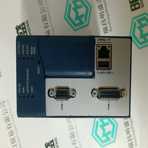
PROSOFT MVI56-PDPMV1 Communication module
- Product ID: MVI56-PDPMV1
- Brand: PROSOFT
- Place of origin: the United States
- Goods status: new/used
- Delivery date: stock
- The quality assurance period: 365 days
- Phone/WhatsApp/WeChat:+86 15270269218
- Email:stodcdcs@gmail.com
- Tags:PROSOFTMVI56-PDPMV1Communication module
- Get the latest price:Click to consult
The main products
Spare parts spare parts, the DCS control system of PLC system and the robot system spare parts,
Brand advantage: Allen Bradley, BentlyNevada, ABB, Emerson Ovation, Honeywell DCS, Rockwell ICS Triplex, FOXBORO, Schneider PLC, GE Fanuc, Motorola, HIMA, TRICONEX, Prosoft etc. Various kinds of imported industrial parts
Products are widely used in metallurgy, petroleum, glass, aluminum manufacturing, petrochemical industry, coal mine, papermaking, printing, textile printing and dyeing, machinery, electronics, automobile manufacturing, tobacco, plastics machinery, electric power, water conservancy, water treatment/environmental protection, municipal engineering, boiler heating, energy, power transmission and distribution and so on.
PROSOFT MVI56-PDPMV1 Communication module
No connection when using the SFD feedback device. CV (Commutation Phase V) input when using open collector Hall feedback. This input has a 2.21 kW pull-up resistor to 3.3 V. J3-6 NC / CW No connection when using the SFD feedback device. CW (Commutation Phase W) input when using open collector Hall feedback. This input has a 2.21 kW pull-up resistor to 3.3 V. Shell Outer shield connection (wired to PE in the drive).The list below describes the factory default functions for each of these inputs. A logic input hardware is active when current is flowing through its photo diode. Inactive logic input hardware is open circuited (has no photo diode current). The active control logic polarity of each input can be set by the corresponding DInpXPol NV Parameter. In other words, depending on the state of DinpXPol, a given hardware input driven active, will activate or not activate a drive control function. DINP1 (ENABLE) Input 1: The ENABLE control function mapped to this input enables/disables the drive and resets the latched drive faults. With default logic polarity (DInp1Pol = Normal), the drive can enable when input 1 is activated (current flowing in the photo diode) and will be disabled when open circuited. This input will disable a drive independent of any other parameters. Successful enabling requires no drive faults and SWEnable, SynqNet drive enable active as appropriate. Setting this input to the inactive state clears any latched drive faults.
DEFAULT INPUT FUNCTIONS
The INHIBIT+ control function mapped to this input prevents further motion in the clockwise shaft motion direction when activated by current flowing in the photo diode. This input has no effect on motion in the counterclockwise direction. This function can be turned on or off by setting EnhibitCW. DInp2Pol sets the control logic active polarity for this hardware input. This input is useful for a clockwise over travel limit switch. Broken wire “failsafe” over travel limit switch operation requires that DInp1Pol be set to Invert by the user to change the factory default. NOTE: For S200 drives with the SynqNet option, the base drive INHIBIT+ function is turned off by EnhibitCW = Off. Over travel limit switch inputs must be wired directly to J13 on the SynqNet option card. DINP3 (INHIBIT-) Input 3: This input operates symmetrically to DINP2 with the INHIBIT- control function preventing further motion in the counter-clockwise shaft motion direction. This function can be turned on or off by setting EnInhibitCCW. DInp3Pol sets the control logic polarity. DINP4 (DIRECTION) Input 4: This input is the direction input when the drive is in Position Mode with the PosCmdSrc set to Step & Direction. Open circuit/no LED current positively increments the position command/motor goes CW. Set up time for direction is 100 µs. Minimum pulse width is 200 µs. Refer to DInp4. 6.7.1.2. DRIVING THE GENERAL PURPOSE INPUTS Sinking Logic For compatibility with sinking outputs, the DINP COM terminal is connected to the positive terminal of a power source (4.0 to 30 VDC). The input (DINP1-4) is connected to the sinking logic output of the field device as shown in the diagram below.