Home > Product > PLC programmable module > BENTLY 3500/33 149986-01 Monitor module
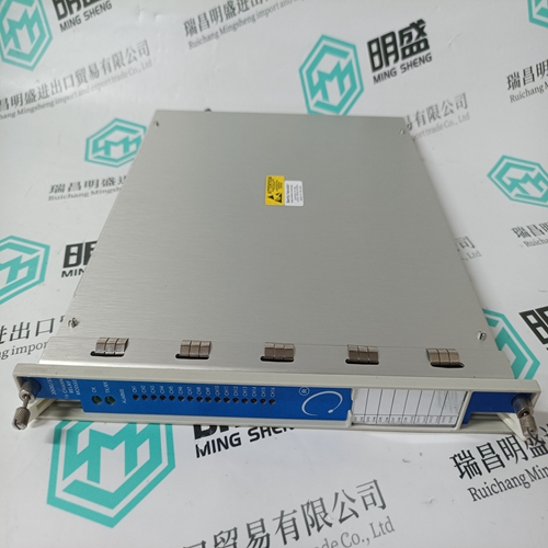
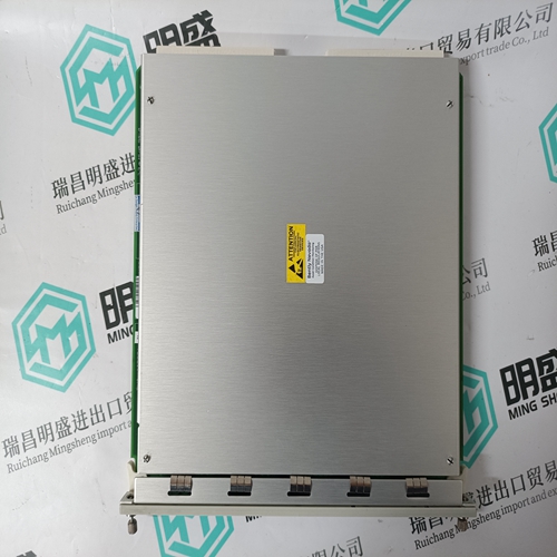
BENTLY 3500/33 149986-01 Monitor module
- Product ID: 3500/33 149986-01
- Brand: BENTLY
- Place of origin: the United States
- Goods status: new/used
- Delivery date: stock
- The quality assurance period: 365 days
- Phone/WhatsApp/WeChat:+86 15270269218
- Email:stodcdcs@gmail.com
- Tags:BENTLY3500/33 149986-01Monitor module
- Get the latest price:Click to consult
The main products
Spare parts spare parts, the DCS control system of PLC system and the robot system spare parts,
Brand advantage: Allen Bradley, BentlyNevada, ABB, Emerson Ovation, Honeywell DCS, Rockwell ICS Triplex, FOXBORO, Schneider PLC, GE Fanuc, Motorola, HIMA, TRICONEX, Prosoft etc. Various kinds of imported industrial parts
Products are widely used in metallurgy, petroleum, glass, aluminum manufacturing, petrochemical industry, coal mine, papermaking, printing, textile printing and dyeing, machinery, electronics, automobile manufacturing, tobacco, plastics machinery, electric power, water conservancy, water treatment/environmental protection, municipal engineering, boiler heating, energy, power transmission and distribution and so on.
BENTLY 3500/33 149986-01 Monitor module
Enables or disables the hardware input that prevents motion in the clockwise direction. When enabled and the hardware input is active, current/torque operation clamps the current command to be 0 or negative/counter clockwise. With a velocity loop, function enabled, and the hardware input active the velocity command is clamped to be 0 or negative/counter clockwise. When both InhibitCCW and InhibitCW are enabled and both hardware inputs are active, the motion command is clamped to 0. 0 - OFF 1 - ON FBSrc Base Unit Feedback, Option Card Feedback (Option Card Only) Supported over SynqNet. Enables When this bit is set to the Option Card Feedback position, it disables both the SFD and Hall feedback faults and device interfaces on the base unit. This bit also forces the feedback position word from the SFD to be zero. The drive is set for sine commutation. In this mode, writing to the CommOff parameter will change the motor position. This mode is used when an Option card is attached and the primary feedback device is a Comcoder. 0 - Base Unit feedback device connected. 1 - Option card feedback device connected. FltDiag Off or Diagnostic Blink Code FltDiag selects between the DOUT1 (Fault) line being static low for no fault and static high for drive off and/or faulted, to low for no fault and toggle high low N number of times with the diagnostic LED fault blink code. The DOUT1 line output is still static high for drive off. See FaultCode entry for a chart giving the blink counts for each fault.
Not supported over SynqNet.
GearOut is used to scale the input position command when configured as a position controller (OpMode = Position). This parameter is the dividend used to calculate the revs per step for the position mode. Typically, this parameter is 256, which allows GearIn to be numerically equal to the number of steps per rev. GearOut negative reverses the direction of motion for a given command. The formula for calculating motor shaft revs per input step is: [GearOut/GearIn]/256 = revs per input step There is 1 input count per step input or per input quadrature count depending on the position command source selected by PosCmdSrc. See Also: GearIn and OpMode. HSInp1Pol Invert or Normal This parameter selects the polarity of the HSInp1. When this parameter is set, the input to the FPGA is inverted before it is used by the logic. This parameter affects the sense of the HSInp1 I/O input. 0 - Normal 1 - Invert I2TF0 23.16e-6 – 1.470 Hz I2T0 sets the break frequency in Hz for the I2T filter used to protect the motor coils from transient thermal overload caused by very high peak currents compared to the motor’s continuous current capability. I2Tf0 should be set based on the motor coil’s thermal time constant. However, typical motor data sheets only give the thermal time constant for the entire motor (coil+back iron+housing) and no data for the coil’s time constant. Since the coil thermal time constant is much faster than the entire motor time constant I2Tf0 is typically set to between 4 and 10 times faster than the motor’s bulk thermal time constant published in the data sheet. G
