Home > Product > Servo control system > Woodward EASYGEN-3500-5 P2 8440-2145 Speed controller
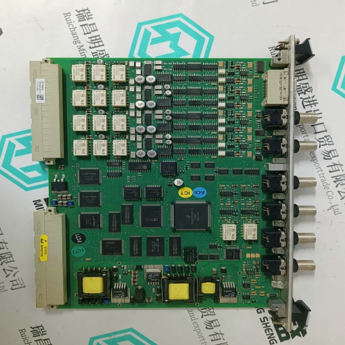
Woodward EASYGEN-3500-5 P2 8440-2145 Speed controller
- Product ID: EASYGEN-3500-5 P2 8440-2145
- Brand: WOODWARD
- Place of origin: the United States
- Goods status: new/used
- Delivery date: stock
- The quality assurance period: 365 days
- Phone/WhatsApp/WeChat:+86 15270269218
- Email:stodcdcs@gmail.com
- Tags:WoodwardEASYGEN-3500-5 P28440-2145Speed controller
- Get the latest price:Click to consult
The main products
Spare parts spare parts, the DCS control system of PLC system and the robot system spare parts,
Brand advantage: Allen Bradley, BentlyNevada, ABB, Emerson Ovation, Honeywell DCS, Rockwell ICS Triplex, FOXBORO, Schneider PLC, GE Fanuc, Motorola, HIMA, TRICONEX, Prosoft etc. Various kinds of imported industrial parts
Products are widely used in metallurgy, petroleum, glass, aluminum manufacturing, petrochemical industry, coal mine, papermaking, printing, textile printing and dyeing, machinery, electronics, automobile manufacturing, tobacco, plastics machinery, electric power, water conservancy, water treatment/environmental protection, municipal engineering, boiler heating, energy, power transmission and distribution and so on.
Woodward EASYGEN-3500-5 P2 8440-2145 Speed controller
This header shows that the file contains data for the S200-SynqNet drive that is located on Node 3. The header also specifies that the drive has firmware version 2.0a. If the drive does not have this version, an error message will be displayed. The rest of the file consists of parameter command strings followed by their values. For an example, see the Sample Drive Map File. The easiest way to create a template for the drive configuration file is to read a file of data from a drive. It is important that the map file exists and is valid.S200 drives are not shipped with a connector kit or serial communication cable. Customers are responsible for ordering the proper connector kit(s) and other accessories necessary for drive setup. For assistance in proper selection, please contact a sales representative.Mechanically-jammed motor. Motion profile acceleration requires peak current for too long of a time duration. Machine load on the motor increased by friction. Wiring problem between drive and motor yielding improper motion. Motor commutation error. Drive under-sized for application, friction or load.
DIAGNOSTICS AND TROUBLESHOOTING
The S200 drive incorporates: Output motor short circuit protection line-to-line, line-to-neutral and line-to-PE. Internal monitoring of the power stage heat sink temperature for drive overtemperature. Bus over-voltage and under-voltage detection. Control under voltage detection. Excessive current I*t fault/foldback. Depending on drive setup, when excessive I*t is detected either the peak output current limit is dropped to 67% of maximum or the drive faults. Excessive motor current I 2 t protection. Invalid smart feedback device (SFD) shaft feedback signal. Motor over temperature on SFD equipped motors. Option card detected faults e.g. Aux Feedback interface faults.The following sequence occurs when the protection circuits generate a fault. One or more faults are detected by the control logic The fault source is latched – only for latched faults The output stage is disabled. The LED indicates the appropriate fault code. For non-latched faults when the fault condition is cleared the drive re-enables automatically. Latched faults are cleared by setting the Enable/ input to the disable state or by cycling (off/on) the Control Power. NOTE: The large bus capacitors store substantial energy. To use the control power to reset a fault, the power should be removed for at least 30 seconds to ensure that the fault resets. Selfresetting faults disable the drive and do not return it to normal operation until 50-100 ms after the fault condition clears. When multiple faults occur, the highest priority fault is reported. After that fault is cleared and the drive is reset by cycling the enable input, the next highest priority fault that still exists will be displayed.

