Home > Product > Gas turbine system > GE VMIVME-5567 Multiplexer switch module
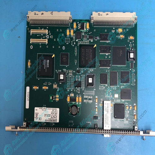
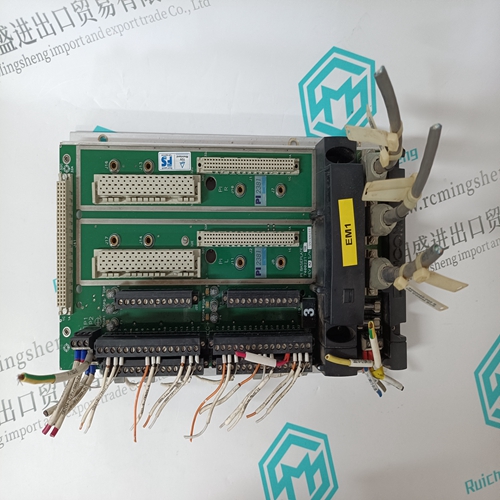
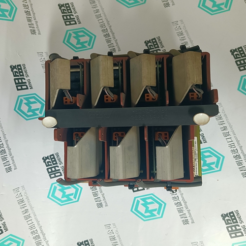
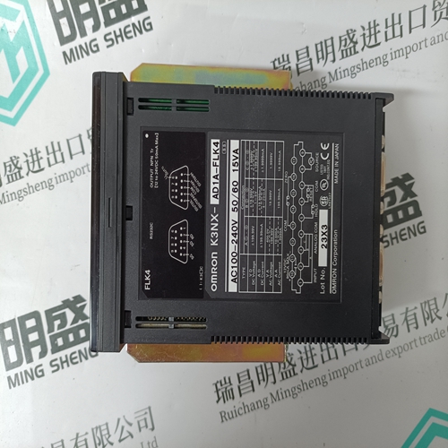
GE VMIVME-5567 Multiplexer switch module
- Product ID: VMIVME-5567
- Brand: GE
- Place of origin: The United States
- Goods status: new/used
- Delivery date: stock
- The quality assurance period: 365 days
- Phone/WhatsApp/WeChat:+86 15270269218
- Email:stodcdcs@gmail.com
- Tags:GEVMIVME-5567Multiplexer switch module
- Get the latest price:Click to consult
GE VMIVME-5567 Multiplexer switch module
Label each CT wire with the phase and polarity that you think it should be. Even though this identification may prove to be incorrect, this step is necessary so that the individual wires can be identified during the description of the procedure. 3. Disconnect the phase B CT wires from terminals 6 and 7. Connect these two wires together using a small screw and nut and tape the connection. 4. Disconnect the phase C CT wires from terminals 8 and 9. Connect and tape these two wires together as in Step 3. 5. Connect the two wires from the phase A CT to the phase A input terminals 4 and 5.
Load Calibration Adjustment
For this procedure, the generator must be running isochronously and not paralleled. Start the prime mover and apply full load. With the Watch Window at the B** DISPLAY LOAD INFO ** sheet and observe 02 LOAD SENSOR INPUT (KW). If this reading does not match external instrumentation, adjust calibration gain and offset under the Service Menu M**LOAD SENSR AND DROOP** until Watch Window value matches metering. The values should match at all intermediate points.


![]()

Professional seller
Professional sales of major electrical brand products in the world
Overseas direct purchase of products, authentic inventory, price concessions
After sales warranty, complete models, same products, different prices and services
This article from the temporal Ming sheng automation equipment co., LTD., reproduced please attach this link: http://www.stockdcs.com/
