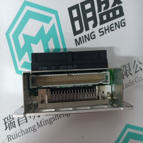
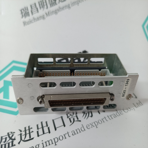
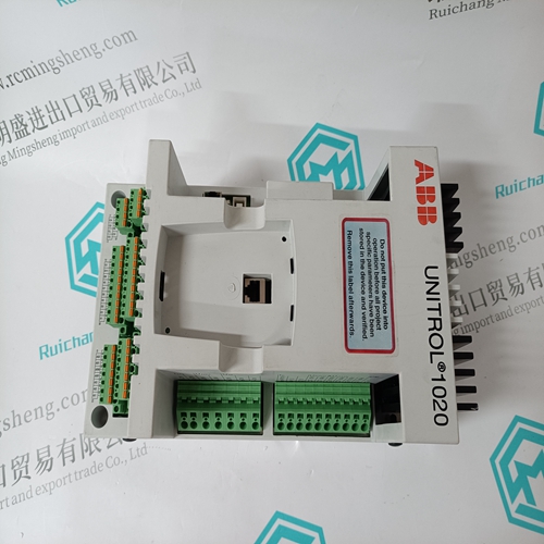
Home > Product > PLC programmable module > NI SCXI-1349 Output interface card
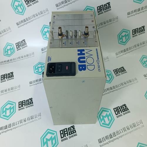
NI SCXI-1349 Output interface card
- Product ID: SCXI-1349
- Brand: NI
- Place of origin: the United States
- Goods status: new/used
- Delivery date: stock
- The quality assurance period: 365 days
- Phone/WhatsApp/WeChat:+86 15270269218
- Email:stodcdcs@gmail.com
- Tags:NISCXI-1349Output interface card
- Get the latest price:Click to consult
The main products
Spare parts spare parts, the DCS control system of PLC system and the robot system spare parts,
Brand advantage: Allen Bradley, BentlyNevada, ABB, Emerson Ovation, Honeywell DCS, Rockwell ICS Triplex, FOXBORO, Schneider PLC, GE Fanuc, Motorola, HIMA, TRICONEX, Prosoft etc. Various kinds of imported industrial parts
Products are widely used in metallurgy, petroleum, glass, aluminum manufacturing, petrochemical industry, coal mine, papermaking, printing, textile printing and dyeing, machinery, electronics, automobile manufacturing, tobacco, plastics machinery, electric power, water conservancy, water treatment/environmental protection, municipal engineering, boiler heating, energy, power transmission and distribution and so on.
NI SCXI-1349 Output interface card
Deactivation of the df/dt protection function, option C
If instability in the speed loop control system occurs,
resulting in jitter on the voltage signals (fast instability
typically occurs if the governor is responding to engine
firings), and it is not possible to adjust this on the governor, or in applications with much noise and harmonic
distortion (frequency converters), the df/dt protection
function can be activated resulting in NO sync. pulse. If
this is the case, and the switchgear is properly protected against wrong synchronisation, the df/dt protection
function can be disabled. Please note that when this
function is disabled, noise on the busbar and the generator inputs of the HAS-111DG can, at worst, result in
a 180 ° out-of-phase synchronisation.
Continuous sync. pulse, option D
When implemented, the sync. relay contact will stay on
as long as the conditions are OK. The following will
deactivate the relay: If the voltage gets outside the
settings on the potentiometer marked VOLTAGE, or the
phase angle gets outside the set phase window, or if
the busbar or the generator voltage drops below 80 %
or goes higher than 120 % of nominal voltage.
Functionality with option B enabled
Whenever the status of the generator or busbar conditions are changed, the sync. relay output is reset. If the conditions are still OK, the relay is activated again after 1 s. For example, in case of dead bus on one side, the sync. relay will be activated and the breaker closed. Now, the HAS-111DG will “see” a new situation (voltage on both sides of the breaker), a reset will be carried out, and after 1 s the relay is activated again. In this case, the sync. relay output cannot be used to operate contactors directly. Voltage difference analogue output, option F This output is standard 0 to 5 to 10 V corresponding to 80 to 100 to 120 % of Unom for controlling of the LSU122DG. If option E is selected, the output is changed to -10 to 0 to 10 V corresponding to 90 to 100 to 110 % of Unom for control of the units in the Multi-line series, for example PPU/GPC.
ULTRA3000 SERVO
· Continuous output power of 110V…460V (0.25…22 kW) · 100…480V AC options, single and three-phase input · SERCOS interface or DeviceNet connectivity options · 7.5…150 A peak current capability · Uses standard high-density D-Shell connectors · Field-programmable flash memory firmware storage · Eight selectable general purpose inputs · Four selectable general purpose outputs and relay output · One serial port for RS-232 or RS-485 communications · Built-in support for multi-turn absolute encoders or an option to supply external logic power to maintain position during power loss
This document describes about Models ALR111 and ALR121 Serial Communication Modules (for FIO) that a field control station (FCS) uses to perform serial communication with subsystems such as FA-M3. These serial communication modules can be mounted on field control units (AFV30, AFV40, AFV10, and AFF50), ESB bus node unit (ANB10), optical ESB bus node unit (ANB11), and ER bus node unit (ANR10).
HARDWARE SPECIFICATIONS
An FCS collects data from subsystems or sets data with control calculations to subsystems using the builder functions by way of serial communication modules. A communication module selects only one communication function, thus two ports must have identical communication functions. It is not possible to select different communication function for every port. The communication functions and those transmission speeds for each communication module are as shown in the table below
Installations to the ER Bus Node Unit (*1) (*2) No. of ALR111/ALR121/ALE111/ALF111/ALP111 modules: Max. 8 units *1: Mounting on the ER bus node unit is applicable when the FCS’s main memory is 32 Mbyte or more and EB401 firmware revision is R3 or later. *2: Field control units (AFV30 and AFV40) do not support ER bus node unit (ANR10).
The serial communication module communicates with subsystems at the specified intervals and stores the subsystem data in the communication modules’ I/O image area. FCS accesses the communication module asynchronously from them, and refers to or sets the I/O images. This enables FCS to use the subsystem data through the I/O terminals of the function block in the same way as the general analog and digital I/O signals.
