Home > Product > DCS control system > RH924YF base module
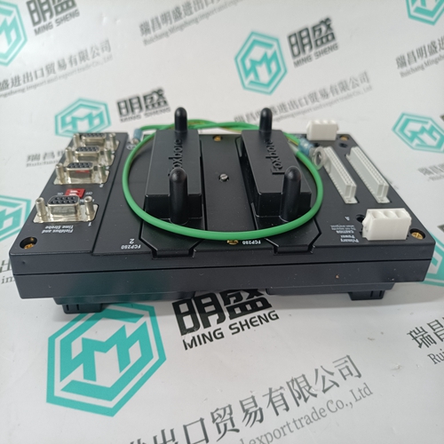
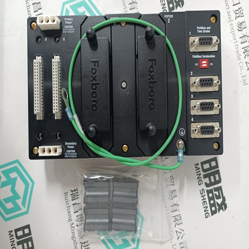
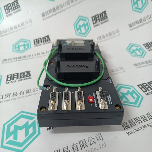
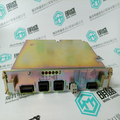
RH924YF base module
- Product ID: RH924YF
- Brand: FOXBORO
- Place of origin: The United States
- Goods status: new/used
- Delivery date: stock
- The quality assurance period: 365 days
- Phone/WhatsApp/WeChat:+86 15270269218
- Email:stodcdcs@gmail.com
- Tags:RH924YFbase module
- Get the latest price:Click to consult
The main products
Spare parts spare parts, the DCS control system of PLC system and the robot system spare parts,
Brand advantage: Allen Bradley, BentlyNevada, ABB, Emerson Ovation, Honeywell DCS, Rockwell ICS Triplex, FOXBORO, Schneider PLC, GE Fanuc, Motorola, HIMA, TRICONEX, Prosoft etc. Various kinds of imported industrial parts
Products are widely used in metallurgy, petroleum, glass, aluminum manufacturing, petrochemical industry, coal mine, papermaking, printing, textile printing and dyeing, machinery, electronics, automobile manufacturing, tobacco, plastics machinery, electric power, water conservancy, water treatment/environmental protection, municipal engineering, boiler heating, energy, power transmission and distribution and so on.
RH924YF base module
FA-M3 Communication Connected device: Personal computer link module F3LC11-1N, F3LC11-2N (FA-M3) LC01-0N, LC02-0N (FA500) Connection method: Connect a personal computer link module with ALR111 or ALR121 communication port. Applicable device: FA-M3, FA500 Transmission protocol: FA-M3 dedicated control protocol No. of subsystem stations: Max. 30 stations/port
Applicable N: Not applicable *1: As for FA500, this is equivalent to the common register. *2: This device is for FA-M3. *3: FA-M3 is able to write data to other link devices than the one assigned to the local station; however, the data will be overwritten upon refreshing by other stations.
Modbus Communication
Connected device: Serial transmission interface module Connection method: Connect an ALR111 or ALR121 module communication port with serial transmission interface module Applicable devices: By Yokogawa - STARDOM FCN, FCJ, and GC1000 Mark II (*1) By Schneider Electric - Modicon484, 584, 584L, 884, 984, 984A, 984B, 984X, and Micro 84 By Yasukawa Electric - Memocon-SC U84, 584, 684H, 694H, R84H-M, GL60S, and GL20 Transmission protocol: Modbus protocol (RTU mode) No. of subsystem stations: Max. 30 stations/port
Connected device: MELSEC-A computer link unit AJ71C24-S8/S6/S3, AJ71UC24, A1SJ71UC24-R2/R4/PRF, A1SJ71C24-R2/R4/PRF, A1SCPUC24-R2, A2CCPUC24 (PRF) Connection method: Connect a computer link unit with ALR111 or ALR121 communication ports Applicable devices: MELSEC-A CPU unit (A communication with FCS can be established with if a CPU is connectable with MELSEC-A computer link unit.) Transmission protocol: MELSEC-A dedicated control protocol format 4 No. of subsystem stations: Max. 30 stations/port
Functional Overview
When the communication function complies, the dual-redundant configuration (*1) can be provided by setting the serial communication modules to dual-redundant. Each of the ALR111 and ALR121 modules has two ports; however, the dual-redundant communication requires two communication modules. The two sets of dual-redundant communication are enabled by two ports of ALR111/ALR121; however, the communication control is defined by each communication module. When one of the communication ports detects an error, both ports switch over the control/stand-by sides to the redundant module. Note that the one-shot write specification cannot be used when dual-redundant communication is set. *1: Refer to “Table Communication Functions Communication Modules.” Data Input Flow Each of the two ALR111/ALR121 modules communicates with the subsystem and reads the subsystem input image data into the module. An FCS accesses the control communication module to read and use these data; however, it does not access the standby communication module. When the FCS detects a control communication module error or subsystem communication failure, the FCS switches its control to the standby module from which to read data.
Data Output Flow
A control communication module outputs data to a subsystem. The control communication module writes data to the subsystem at the specified intervals when an FCS sets the data in it. Meanwhile, the standby communication module re-reads and retains the output image data when it accesses the subsystem at the specified interval. This equalizes the data between the control and standby communication modules. When an error is detected, the FCS switches its control to the stand-by module through which the FCS continues to output data to the subsystem.
