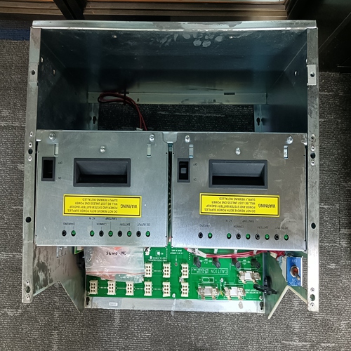
Home > Product > DCS control system > TRICONEX AIH 3723X Enhanced communication card
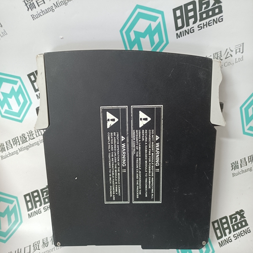
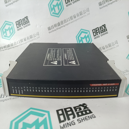
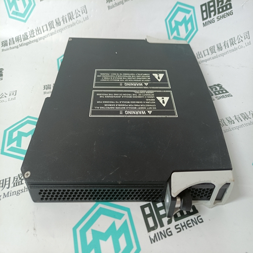
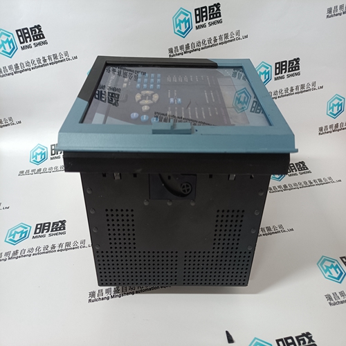
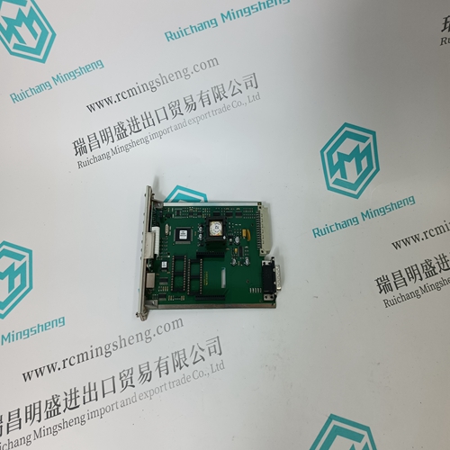
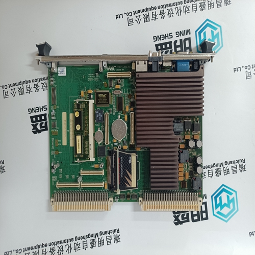
TRICONEX AIH 3723X Enhanced communication card
- Product ID: AIH 3723X
- Brand: TRICONEX
- Place of origin: The United States
- Goods status: new/used
- Delivery date: stock
- The quality assurance period: 365 days
- Phone/WhatsApp/WeChat:+86 15270269218
- Email:stodcdcs@gmail.com
- Tags:TRICONEX AIH 3723XEnhanced communication card
- Get the latest price:Click to consult
The main products
Spare parts spare parts, the DCS control system of PLC system and the robot system spare parts,
Brand advantage: Allen Bradley, BentlyNevada, ABB, Emerson Ovation, Honeywell DCS, Rockwell ICS Triplex, FOXBORO, Schneider PLC, GE Fanuc, Motorola, HIMA, TRICONEX, Prosoft etc. Various kinds of imported industrial parts
Products are widely used in metallurgy, petroleum, glass, aluminum manufacturing, petrochemical industry, coal mine, papermaking, printing, textile printing and dyeing, machinery, electronics, automobile manufacturing, tobacco, plastics machinery, electric power, water conservancy, water treatment/environmental protection, municipal engineering, boiler heating, energy, power transmission and distribution and so on.
TRICONEX AIH 3723X Enhanced communication card
The program folder also contains a help file that describes the configuration and handling of your control electronics. After having installed the BODAC software, proceed as follows: 1. Connect the serial interface cable (mat. no. R900776897) to the port of the control electronics VT-VPCD. 2. Plug the serial interface cable into the serial interface (COM) port of your PC or, if required, use a USB converter – Mat. no. R901066684. The control electronics VT-VPCD and the PC are now connected. 3. Start software BODAC. 4. Perform the software-sided startup as described in the online documentation and RE 30028-01-B.
Indicator/operating elements and ports of the control electronics The operating elements and ports on the front panel of the control electronics VT-VPCD can be used to query settings and parameters, connect external test instruments or connect the control electronics to a PC. For a detailed description of indicator and operating elements, see Chapter 5.2.3 “Display and operating elements and test sockets“ on page 23.
Menu tree for setup and parameters
The display is used for indicating command values and actual values as well as errors. For making any settings or parameter changes, BODAC has to be used. The following overviews are given on the next few pages: • Menu tree “Parameters” • Menu tree “Setup” • Menu tree “Analog I/O” part 1 • Menu tree “Analog I/O” part 2 • Menu tree “Analog I/O” part 3 • Menu tree “Faults“ • Menu tree “Test jacks“ By pressing the key combination “Enter” and “ESC” you get to a menu with several entries at Level 1: “Setup“, “Analog I/O“, “Faults“ and “Test jacks“. Hold the keys depressed for about 5 seconds.
Changes to the bus ID require a re-initialization of the control electronics. After having successfully saved any changes to the bus ID, switch the electronics off and on again.
Operating the control electronics VT-VPCD
To make operations directly on the control electronics you can use the four control keys “UP”, “DOWN”, “ENT” and “ESC”. With the help of these control keys you can quickly and easily check, modify or optimize parameters and settings on the control electronics.
Before changing any parameters or settings, make yourself familiar with the menu structure of your control electronics. Please read the preceding Chapter 9.1.1 “Menu tree for setup and parameters“ on page 39. Meaning of control keys: Use the “UP” key to move upwards within the available menu items at the selected level. Use the “DOWN” key to move downwards within the available menu items at the selected level. Function for changing the control electronics mode: Hold the “ENT” control key down for more than 2 seconds to change to the configuration mode “EDIT Parameters”. Configuration level function: The “ENT” control key brings you to the next lower level in the menu structure or confirms any values entered. New values entered will only be stored in the memory after you returned to level 0 (display of the manufacturer’s name)! This saving process takes about one minute. During this time, do not switch off the power supply to the control electronics, otherwise, the changes you made will not be stored in the memory.
