Home > Product > Servo control system > WOODWARD 8200-226 governor
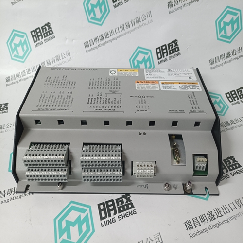
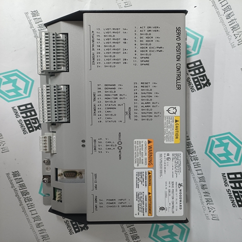
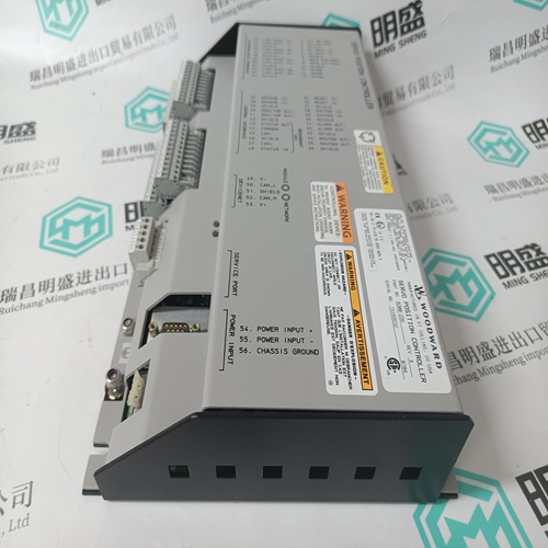
WOODWARD 8200-226 governor
- Product ID: 8200-226
- Brand: WOODWARD
- Place of origin: the United States
- Goods status: new/used
- Delivery date: stock
- The quality assurance period: 365 days
- Phone/WhatsApp/WeChat:+86 15270269218
- Email:stodcdcs@gmail.com
- Tags:WOODWARD 8200-226governor
- Get the latest price:Click to consult
The main products
Spare parts spare parts, the DCS control system of PLC system and the robot system spare parts,
Brand advantage: Allen Bradley, BentlyNevada, ABB, Emerson Ovation, Honeywell DCS, Rockwell ICS Triplex, FOXBORO, Schneider PLC, GE Fanuc, Motorola, HIMA, TRICONEX, Prosoft etc. Various kinds of imported industrial parts
Products are widely used in metallurgy, petroleum, glass, aluminum manufacturing, petrochemical industry, coal mine, papermaking, printing, textile printing and dyeing, machinery, electronics, automobile manufacturing, tobacco, plastics machinery, electric power, water conservancy, water treatment/environmental protection, municipal engineering, boiler heating, energy, power transmission and distribution and so on.
WOODWARD 8200-226 governor
Hysteresis In order to avoid "chatter" on the relay contacts the contact functions are provided with a hysteresis, that is a difference of 2 % of full scale between energising and de-energising of the relay. Power-up/power-down circuits The RMC-121D is provided with a 200 ms power-up circuit, ensuring the correct function of the relay on connection of the auxiliary voltage. INFO Normally energised contacts are not activated (contact does not open/close) until 200 ms after connection of the auxiliary voltage. Likewise, the RMC-121D is provided with a 200 ms power-down circuit, ensuring supervision and maintenance of any set point exceedings for 200 ms after disconnection of the auxiliary voltage. INFO A special version is available where the 200 ms power-down is enlarged to 1 sec.
The English version of this document always contains the most recent and up-to-date information about the product. DEIF does not take responsibility for the accuracy of translations, and translations might not be updated at the same time as the English document. If there is a discrepancy, the English version prevails.
Safety instructions
Do not attempt any work on a powered drive. After switching off the mains, always allow the intermediate circuit capacitors 5 minutes to discharge before working on the frequency converter, the motor or the motor cable. It is good practice to check (with a voltage indicating instrument) that the drive is in fact discharged before beginning work. Avoid touching the circuit board (RMIO) inside the RDCU unit in order to minimise the risk of damage caused by static electricity. Do not use excessive force when detaching connectors or removing the cover of the unit. Identifying different types of unit Before installation, check that the RDCU unit has the correct application program for the converter hardware in question. There is a label attached to the cover of the RDCU unit that lists “SW TYPE”, “SW CODE” and “DEVICE TYPE”. “SW TYPE” identifies the application program that is loaded into the RDCU unit. Some of the most common “SW TYPE” codes are AMXRxxxx (ACS800 System Application Program), ASxRxxxx (ACS800 Standard Application Program), AHxRxxxx (ACS800 Pump Control Application Program), and IxxRxxxx (IGBT Supply Unit Application Program). Check that the application program corresponds to the original order. Check also that the “DEVICE TYPE” indicated matches that of the converter hardware.
Mechanical installation
General The RDCU unit can be mounted on a vertical or horizontal 35 × 7.5 mm DIN rail. The unit should be mounted so that air can freely pass through the ventilation holes in the housing. Mounting directly above heat-generating equipment should be avoided. WARNING! Avoid installing the RDCU in the immediate vicinity of sources of electromagnetic disturbance, such as relays, contactors, brake choppers and motor cabling. The minimum recommended distance from such components is 500 mm. Installing metallic screening between the unit and the source of disturbance is highly recommended, and may reduce the required distance. The RDCU is grounded to the mounting rail by two screws. Fastening the unit to the mounting rail Note: Set jumper J1 (if necessary; see the Isolation and grounding diagram) before fastening the unit.
