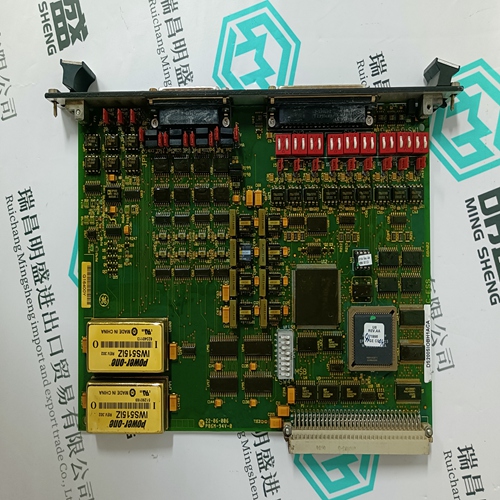
Home > Product > Gas turbine system > IC695CRU320CA-EL Gas turbine module
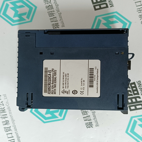
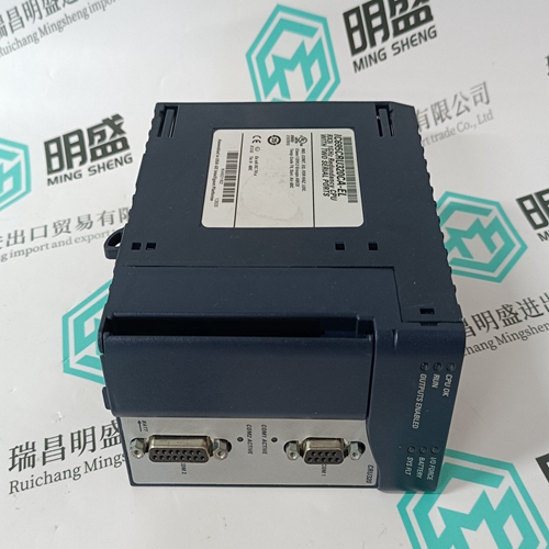
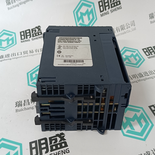
IC695CRU320CA-EL Gas turbine module
- Product ID: IC695CRU320CA-EL
- Brand: GE
- Place of origin: the United States
- Goods status: new/used
- Delivery date: stock
- The quality assurance period: 365 days
- Phone/WhatsApp/WeChat:+86 15270269218
- Email:stodcdcs@gmail.com
- Tags:IC695CRU320CA-ELGas turbine module
- Get the latest price:Click to consult
The main products
Spare parts spare parts, the DCS control system of PLC system and the robot system spare parts,
Brand advantage: Allen Bradley, BentlyNevada, ABB, Emerson Ovation, Honeywell DCS, Rockwell ICS Triplex, FOXBORO, Schneider PLC, GE Fanuc, Motorola, HIMA, TRICONEX, Prosoft etc. Various kinds of imported industrial parts
Products are widely used in metallurgy, petroleum, glass, aluminum manufacturing, petrochemical industry, coal mine, papermaking, printing, textile printing and dyeing, machinery, electronics, automobile manufacturing, tobacco, plastics machinery, electric power, water conservancy, water treatment/environmental protection, municipal engineering, boiler heating, energy, power transmission and distribution and so on.
IC695CRU320CA-EL Gas turbine module
Ground concept and power supplies Ground concept All CS 31 products in a cabinet must be connected to the same earth. When the remote units are outside the cabinet, they must be connected to the nearest earth. The connection to the earth has to be as short as possible (shorter than 25 cm)
The capacitor is integrated in the plug-in base. When the cabinets are close from each others, the different earths have to be connected together with a cable with a cross section of at least 16 mm2 .
The noisy elements (drives, motors, ...) haven't to be connected to the earth between two cabinets. The connection to the earth has to be near the noisier element.Power supply I-T - The neutral is isolated from the earth - The metallic parts are connected to the earth In a noisy environnement, an isolated transformer with a shield has used in each cabinet (even for 24 VDC version).
Types of power supplies
Different types of power supplies are available. The main difference is the connection of the neutral and the metallic parts to the earth. Power supply T-T – The neutral is connected to the earth. All metallic parts are connected to the earth One single CPU is the master on the bus, all of the other remote units or CPU are considered to be slaves. The master CPU manages up to a maximum of 31 remote units on one bus. All messages are terminated with an error check (CRC8).
During initialization, the central unit interrogates all of the remote units in succession, thus building an image of the system configuration. On each cycle of the bus all of the remote units are interrogated. This updates all diagnosis information and recognizes additional remote units. If the CPU or one of the remote units receives a message with a (CRC8) error, it is ignored. After ten consecutive transmission errors, an error "Bus error" is generated on the remote units and within the diagnosis of the central unit.
Bus refresh time
The refresh time depends on the configuration of the system, number and type of remote units. The example below is for a system of remote units type ICSC 08 L1 : The user program and the bus refresh cycle are executed in serie with the 07 KR/KT 31, 07 KR 91 and 07 KT 92/93 central units. The time event diagram is shown below : ● Bus refresh time (T rb) The bus transmission time is easily calculated from the configuration of the installation. This time is equal to : – with a master central unit serie 90 : T rb = T offset + T communication time – with a master central unit serie 30 : T rb = T offset + T communication time + n * 100 (µs) with : – T offset = 2 000 µs – T communication time : see table on the next page – n = number of slaves on the bus Example of calculation Configuration : 1 "Master" CPU .........2 000 µs 1 ICSK 20 F1................452 µs 1 ICSO 08 R1 ............... 260 µs 1 ICSI 16 E1 ................. 387 µs 1 ICFC 16 L1 ................516 µs 1 ICSC 08 L1................387 µs – with a master central unit serie 90 T rb = 4 002 µs = 4 ms – with a master central unit serie 30 T rb = 4 502 µs = 4,5 ms ● Response time to energize an output from the activation of an input See Part 3 page 5.3-1 for a master central unit serie 30. See Part 4 pages 1-22 or 2-25 or 3-21 for a master central unit serie 90
