Home > Product > DCS control system > SCYC51090 58053899E Interface component
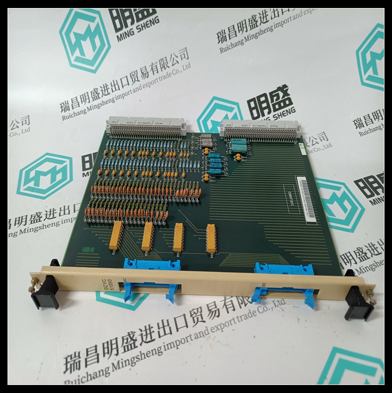
SCYC51090 58053899E Interface component
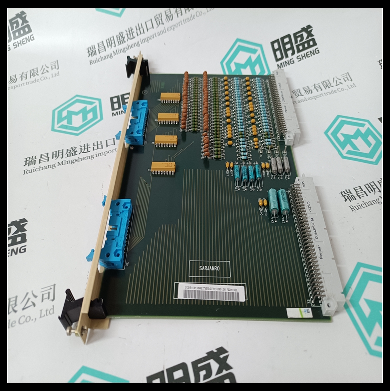
- Product ID: SCYC51090 58053899E
- Brand: ABB
- Place of origin: The Swiss
- Goods status: new/used
- Delivery date: stock
- The quality assurance period: 365 days
- Phone/WhatsApp/WeChat:+86 15270269218
- Email:stodcdcs@gmail.com
- Tags:SCYC51090 58053899EInterface component
- Get the latest price:Click to consult
The main products
Spare parts spare parts, the DCS control system of PLC system and the robot system spare parts,
Brand advantage: Allen Bradley, BentlyNevada, ABB, Emerson Ovation, Honeywell DCS, Rockwell ICS Triplex, FOXBORO, Schneider PLC, GE Fanuc, Motorola, HIMA, TRICONEX, Prosoft etc. Various kinds of imported industrial parts
Products are widely used in metallurgy, petroleum, glass, aluminum manufacturing, petrochemical industry, coal mine, papermaking, printing, textile printing and dyeing, machinery, electronics, automobile manufacturing, tobacco, plastics machinery, electric power, water conservancy, water treatment/environmental protection, municipal engineering, boiler heating, energy, power transmission and distribution and so on.
SCYC51090 58053899E Interface component
In case of use of only one external power supply 24 VDC for inputs, the different communs have to be connected together and to the 0 VDC of the power supply. ● Initialization After configured and wired the unit : – the unit initializes itself after power On. – the error led goes out after initialization. – the status of 8 inputs is displayed on the 8 led's.
For the PC board 07 CM 90 and the coupler boards 07 CS 61 and 07 CS 91, refer to their own description The available configuration for each input : – delay ● Fault indication The led's indicate the following : Led 0 : "Unit error" Led 1 : "Bus error" The status of an input channel is shown by : Led 7 : "Input" If an error occurs the red led error is On (see Chapter 9, Volume 2 «In case of failure»)
Binary Input remote unit
● Initialization After configured and wired the unit : – the unit initializes itself after power On. – the error led goes out after initialization. – the status of 8 inputs is displayed on the 8 led's.
Note : The both commun + terminals have to be connected to garanty a right diagnosis function. If the common + terminals are not connected to an external power supply 24 VDC, the corresponding outputs are reset to 0. – A free wheel diode is not necessary because the protection is integrated into the transistor component. – An external thermal fuse max. 10 A has to be connected between the common + terminals and the 24 VDC to avoid damage in case of use of a lot of overload outputs. ● Initialization After configured and wired the unit : – the unit initializes itself after power On. – the error led goes out after initialization. – the status of 16 outputs is displayed on the 16 led's.
Power supply 24 VDC
Almost one common + has to be connected to the power supply. When switching high current loads, use many commun + terminal to avoid damage to the base. Warning : For a version dated before 01/92, the terminals 4 and 5 have not be used. Internal connection Note : In case of use of an external power supply 24 V DC for inputs, the "24" V DC has to be connected to the common "+". Caution : if the 24 V DC is connected to common "+", the remote unit can be supplied by the external power supply even if the main power supply is OFF. ● Initialization After configured and wired the unit : – the unit initializes itself after power On. – the error led goes out after initialization. – the status of 8 inputs is displayed on the 8 led's.