Home > Product > DCS control system > SSA-T8028-0652 switches
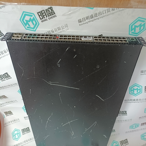
SSA-T8028-0652 switches
- Product ID: SSA-T8028-0652
- Brand: ENTERASYS
- Place of origin: The United States
- Goods status: new/used
- Delivery date: stock
- The quality assurance period: 365 days
- Phone/WhatsApp/WeChat:+86 15270269218
- Email:stodcdcs@gmail.com
- Tags:SSA-T8028-0652switches
- Get the latest price:Click to consult
The main products
Spare parts spare parts, the DCS control system of PLC system and the robot system spare parts,
Brand advantage: Allen Bradley, BentlyNevada, ABB, Emerson Ovation, Honeywell DCS, Rockwell ICS Triplex, FOXBORO, Schneider PLC, GE Fanuc, Motorola, HIMA, TRICONEX, Prosoft etc. Various kinds of imported industrial parts
Products are widely used in metallurgy, petroleum, glass, aluminum manufacturing, petrochemical industry, coal mine, papermaking, printing, textile printing and dyeing, machinery, electronics, automobile manufacturing, tobacco, plastics machinery, electric power, water conservancy, water treatment/environmental protection, municipal engineering, boiler heating, energy, power transmission and distribution and so on.
SSA-T8028-0652 switches
If one of these errors occurs, the red LED 3 lights up. The error message is sent to the central unit (or coupler). For more information see the chapters ”Diagnosis” in the descriptions of the central units and couplers. By means of the test button 4 and the LEDs 1 the user is enabled to call diagnosis information directly from the module. Pressing the test button the first time the channel En,00 is selected: The LED of the selected channel flashes, all of the other LEDs are switched off during this test. When releasing the test button, the error information belonging to this channel is displayed by the green LEDs 00 to 07 for a period of ca. 3 seconds. Meaning of the LEDs if lighting up: 00 Error in the module (Unit error) 01 Error on the CS31 system bus (Bus error) 02 not used 03 not used 04 Overload or short circuit, outputs only 05 not used 06 Configuration as an output 07 Configuration as an input The meaning of the diagnosis LEDs 2 is labelled on the front panel of the module in English. Pressing the test button further times, the test procedure repeats for all of the other inputs and outputs (and combined inputs/outputs).
Technical data ICDG 32 L1
In general the technical system data listed in volume 2 of the system description ABB Procontic CS31 are valid for all modules and central units. Additional data or data which are different from the system data are listed as follows.
After calling information from the last channel, a lamp test is carried out by pressing the test button the next time. All LEDs light up. After that, the positions of the address DIL switches stored during the initialization are displayed on the LEDs 00 to 07 for a period of ca. 3 seconds. LED 00 shows the position of switch No. 1 (LEDs 00 to 07 belong to the switches 1 to 8). The error messages in the I/O module and in the central unit are reset again, when the errors have been eliminated, no new errors have occurred and the error elimination has been acknowledged. This also applies for the overload message independent of the position of the DIL switch No. 8. Acknowledging an error after error elimination: – by pressing the test button for a period of ca. 5 seconds or – by means of the TCZ or a PC (see TCZ description in volume 7.3, Terminal mode, Mail command ”Acknowledging errors on remote modules” or – via the PLC program in the central unit, connection element CS31QU, software 907 PC 331.
General data of the module
Admissible temperature range, module in operation 0...65 °C Rated supply voltage 24 V DC Rated signal voltage at inputs and outputs 24 V DC Max. current consumption, outputs unloaded0.15 A Max. total output current 4.0 A Max. rated loadability for the supply terminals 4.0 A Max. power dissipation in the module,
Remarks: Using the LED display for overload/short-circuit, the user can find out which channels are involved. The LEDs 06 and 07 indicate for the 8 configurable channels whether the selected channel is configured as output or as input/output. The unchangeable channels are indicated in the same way. When the calling of the diagnosis information has been terminated, the 32 green and yellow LEDs show the binary signal statuses of the channels again.