Home > Product > DCS control system > YOKOGAWA PW501 input unit module
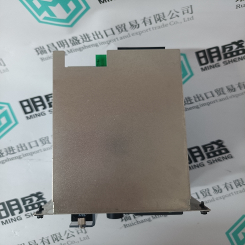
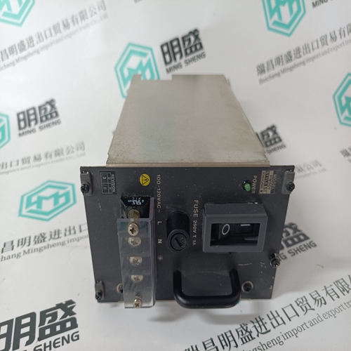
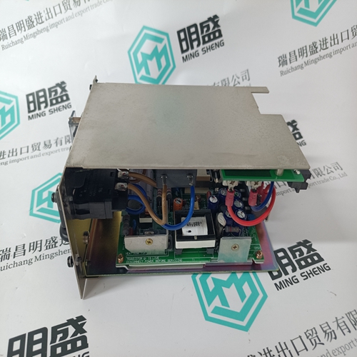
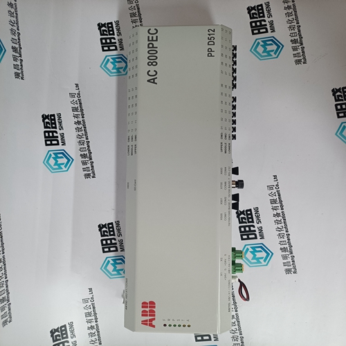
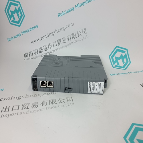
YOKOGAWA PW501 input unit module
- Product ID: PW501
- Brand: YOKOGAWA
- Place of origin: Japan
- Goods status: new/used
- Delivery date: stock
- The quality assurance period: 365 days
- Phone/WhatsApp/WeChat:+86 15270269218
- Email:stodcdcs@gmail.com
- Tags:YOKOGAWAPW501input unit module
- Get the latest price:Click to consult
The main products
Spare parts spare parts, the DCS control system of PLC system and the robot system spare parts,
Brand advantage: Allen Bradley, BentlyNevada, ABB, Emerson Ovation, Honeywell DCS, Rockwell ICS Triplex, FOXBORO, Schneider PLC, GE Fanuc, Motorola, HIMA, TRICONEX, Prosoft etc. Various kinds of imported industrial parts
Products are widely used in metallurgy, petroleum, glass, aluminum manufacturing, petrochemical industry, coal mine, papermaking, printing, textile printing and dyeing, machinery, electronics, automobile manufacturing, tobacco, plastics machinery, electric power, water conservancy, water treatment/environmental protection, municipal engineering, boiler heating, energy, power transmission and distribution and so on.
YOKOGAWA PW501 input unit module
Connection The address of the card is set with the dil switch SW1 in the same manner as the plug-in base. Connect the CS31 bus to the connector X1 of the card with the special cable (YB560105-DZ ABB Robotics) Connect the wires of this cable to the CS31 bus.
Insert the card into a binary input/output slot of the robot rack (refer to robot documentation for user details). For the PC board 07 CM 90 and the coupler boards 07 CS 61 and 35 CS 91, refer to their own description ● Initialization – The card initializes itself after powered on the robot and the CS31. The input led's 1,2,8 et "F" are illuminated. – After a correct initialization, the error led "F" switch off, The input led's take their function, the system is now ready to run
● Utilisation
This card is used like a standard remote binary input/ output unit. The usual instructions are used to read inputs and write outputs. This card is used like two DSQC 223 by the robot. Each output bit of the robot is an input bit of the CS31. Each input bit of the robot is an output of the CS31. Example : The robot sets output 5 to 1. This is read using the input (Exx,05 or Ixx 05). In the same way input 7 of the robot can be set by writing to Axx,07 or Oxx,07 of the CS31. The function of the led's on the front of the card can be selected by pressing the "SELECT" push-button on the card (I/O status or address and diagnosis). – The "I/O1" led is illuminated when the led's indicate the 16 first channels status. – The "I/O2" led is illuminated when the led's indicate the 16 others channels status. – The "ADR" led is illuminated when the led's indicate the setting of SW1. If a fault occurs the "F" led is illuminated and the fault code is displayed on the led's: Led 1 : "Bus error" No initialization on the CS31 bus. Led 2 : "Unit error" No initialization on the robot
● Configurations
The NCC 485 module is an RS232/RS485 interface converter. It is the solution of transmission problems in industrial data communications. The NCC 485 allows a isolated connection between two RS232 interface and an RS485 interface. In half or full duplex protocol, the NCC 485 allows long ranges transfers, the creation of multiple point connection. It is particulary adapted for the connection of the central units 07KR31 and 07KT31 to a MODBUS network.
SW1 – OFF : pin 6 is independant of pin 7 Active mode configuration for CS31 central units. – ON : pin 6 is connected to pin 7 ASCII or MODBUS mode configuration according CS31 central units and value of the system constant KW00,06 (refer to central units descriptions).
