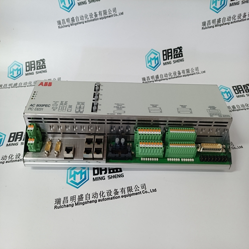
Home > Product > PLC programmable module > 1336F-MCB-SP2G input card
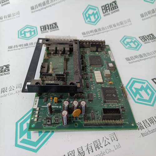
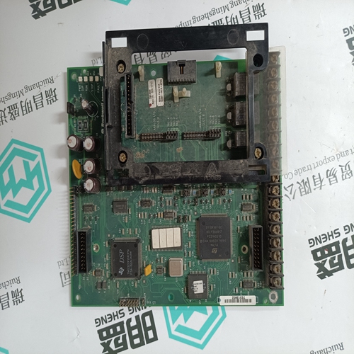
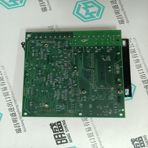
1336F-MCB-SP2G input card
- Product ID: 1336F-MCB-SP2G
- Brand: A-B
- Place of origin: the United States
- Goods status: new/used
- Delivery date: stock
- The quality assurance period: 365 days
- Phone/WhatsApp/WeChat:+86 15270269218
- Email:stodcdcs@gmail.com
- Tags:1336F-MCB-SP2Ginput card
- Get the latest price:Click to consult
The main products
Spare parts spare parts, the DCS control system of PLC system and the robot system spare parts,
Brand advantage: Allen Bradley, BentlyNevada, ABB, Emerson Ovation, Honeywell DCS, Rockwell ICS Triplex, FOXBORO, Schneider PLC, GE Fanuc, Motorola, HIMA, TRICONEX, Prosoft etc. Various kinds of imported industrial parts
Products are widely used in metallurgy, petroleum, glass, aluminum manufacturing, petrochemical industry, coal mine, papermaking, printing, textile printing and dyeing, machinery, electronics, automobile manufacturing, tobacco, plastics machinery, electric power, water conservancy, water treatment/environmental protection, municipal engineering, boiler heating, energy, power transmission and distribution and so on.
1336F-MCB-SP2G input card
Change-over between the application modes – Stand-alone central unit – Bus master central unit and – Intelligent I/O remote unit (Slave central unit) The central unit is set to "Stand-alone" upon delivery. Changing the application mode is carried out in the following three steps : 1. Change the system constant KW 0,0 in the PLC, (see chapter 1.4 "Operands" § System constants). 2. Save the user program in the EEPROM. 3. Activate new application mode by : – calling up the menu item of "Enable PLC mode" in the ABB programming and test system or – performing a warm start or – performing a cold start.
● Setting the cycle time (see chapter 5 "Processing times") ● Addressing when remote units are connected (see chapter 6 "Addressing") ● Initialisation of data storage areas System constants can be used to determine which data areas are to be initialised with the value of "0" during program start-up. A specific initialization is possible for the following areas. It is also possible to initialize partial areas only : – Binary flags – Word flags – Double word flags – Step chains – Historical values (see chapter 1.4 "Operands" § System constants)
● Reactions on errors of error class 3
The user can configure whether or not the user program is to be aborted automatically, if an class 3 error occurs, (see chapter 1.4 "Operands" § System constants). ● Starting-up the CS31 system after power ON The user can enter a number of n remote units in system constant KW 0.9. The user program starts only i.e. it handles process inputs and ouputs only, if at least n remote units have been adopted into the CS31 system bus cycle, (see chapter 1.4 "Operands" § System constants).
Setting the operating modes The constants KW 00,00…KW 00,15 are reserved as system constants. Even the constants KW 00,12…KW 00,15 which are not used yet may under no circumstances be used for other purposes. KW 00,00 : Setting the central unit operating modes, (Stand-alone central unit, Master central unit, Slave central unit) KW 00,01 : Initialization : bit flag area KW 00,02 : Initialization : word flag area KW 00,03 : Initialization : double word flag area
Setting the cycle time KD 00,00
The cycle time of the central unit program is preset with this constant. The cycle time is given in the unit of measurement milliseconds. Only integral multiples of 5 ms are permitted. The maximal value allowed in master configuration is 100 ms and in slave configuration 250 ms. – Error diagnosis Summation error display : M 255,10 indicates, that the central unit has detected an error Fatal error, FK1 : M 255,11 = 1 i.e. error detected, detailed information in MW 254,00…MW 254,07 Serious error, FK2 : M 255,12 = 1 i.e. error detected, detailed information in MW 254,08…MW 254,15 Light error, FK3 : M 255,13 = 1 i.e. error detected, detailed information in MW 255,00…MW 255,07 Warning, FK4 : M 255,14 = 1 i.e. error detected, detailed information in MW 255,08…MW 255,15 – First-cycle detection M 255,15 This binary flag can be used for detection of the first program cycle after a program start. It is always set to "zero" after each program start, independent of the initialization instructions given by the system constants. If this flag is read by the user program and then set to "1", it can be found out whether or not the user program was started once more.
