Home > Product > PLC programmable module > YASKAWA CPS-150F Control the mainboard
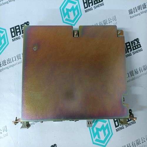
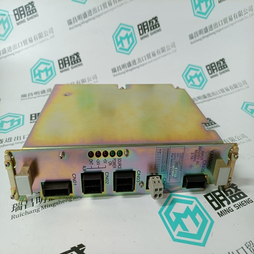
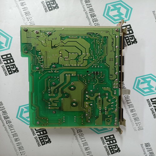
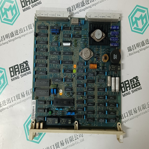
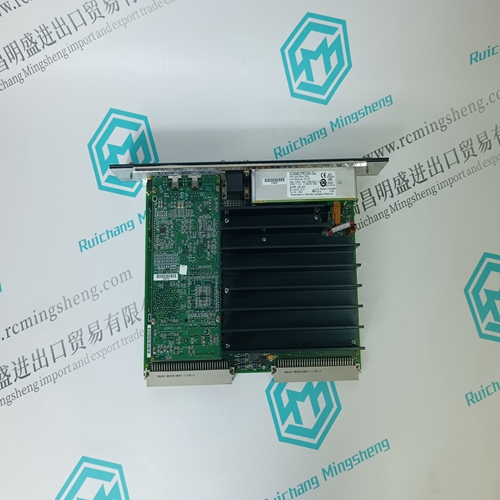
YASKAWA CPS-150F Control the mainboard
- Product ID: CPS-150F
- Brand: YASKAWA
- Place of origin: JAPAN
- Goods status: new/used
- Delivery date: stock
- The quality assurance period: 365 days
- Phone/WhatsApp/WeChat:+86 15270269218
- Email:stodcdcs@gmail.com
- Tags:YASKAWACPS-150FControl the mainboard
- Get the latest price:Click to consult
The main products
Spare parts spare parts, the DCS control system of PLC system and the robot system spare parts,
Brand advantage: Allen Bradley, BentlyNevada, ABB, Emerson Ovation, Honeywell DCS, Rockwell ICS Triplex, FOXBORO, Schneider PLC, GE Fanuc, Motorola, HIMA, TRICONEX, Prosoft etc. Various kinds of imported industrial parts
Products are widely used in metallurgy, petroleum, glass, aluminum manufacturing, petrochemical industry, coal mine, papermaking, printing, textile printing and dyeing, machinery, electronics, automobile manufacturing, tobacco, plastics machinery, electric power, water conservancy, water treatment/environmental protection, municipal engineering, boiler heating, energy, power transmission and distribution and so on.
YASKAWA CPS-150F Control the mainboard
➀ 12 yellow led's labelled "Input" to indicate status of the inputs. ➁ 8 yellow led's labelled "Output" to indicate the presence of the outputs. ➂ 1 green led labelled "Supply" to indicate the presence of the supply ➃ 1 green led "RUN" ➄ 1 red led for the error status ➅ 1 "RUN/STOP" switch to start and stop the program execution ➆ 1 serial interface RS 232 C ➇ Assignment of the indentifiers for the inputs ➈ Assignment of the identifiers for the outputs ➉ The central unit has to be plugged on the plug-in base ECZ. The plug-in base ECZ can be mounted on a DIN rail 35 x 15 mm - EN 50022.
Electrical connection Terminal assigments
Please observe in particular : – The earthing measures – The handling of the electrically isolated input groups – The handling of the electrically isolated output groups – The connection of analog-value receiver and analogvalue sensor – The earthing of the switch cabinet mains socket
For 07 KT 31 – A free wheel diode is not necessary because the protection is integrated into the transistor component. – An external thermal fuse max. 5A has to be connected between the common + terminals and the 24 VDC to avoid damage in case of use of a lot of overload outputs.
Electrical isolation and notes on earthing
The following illustration shows the parts of the device's circuit which are electrically isolated from each other as well as the internal connections which exist. Both the creepage distances and clearances as well as the test voltages used correspond to DIN/VDE 0160. The earth on the plug-in base ECZ has to be connected directly and on the shortest possible way to the switch cabinet earthing using a wire with a cross section of 6 mm2 in order to ensure safe earthing and as an EMC measure
Please observe : – All of the CS31 devices, no matter whether they are master or slave devices, are connected with the twistedpair bus line as follow : - One core of the bus line is looped through via the bus n°2 terminals of the CS31 system bus. - The other core of the bus line is looped through via the BUS 2 terminals of all devices to be connected to the CS31 system bus. – If the central unit 07 KR 31 / 07 KT 31 is located at the beginning or at the end of the bus line, the bus terminating resistor (120 1/4W) has to be connected additionally between the bus n°1 and the bus n°2 terminals. – The shield of the twisted-pair bus line is looped through via the shield terminals of all the devices to be connected to the CS31 system bus. – The handling of the CS31 system bus is described in detail in volume 2, System data.
Central processing units
The central units 07 KR 31 / 07 KT 31 provide a 24VDC (100mA) voltage output for the 12 binary input signals (for this purpose only). This 24V output voltage is only available for the 230 / 120VAC version. The internal 24V power supply is overload-proof. The 24V output voltage is ready for operation again approx. 2 minutes after an overload has been eliminated.
All data (flags, words, historical datas, real-time clock) can be stored in a zeropower RAM (battery included into the RAM). The battery lifetime is 5 years. The battery lifetime is the time during which the device remains operable in order to backup data while the supply voltage of the central is switched off. As long as there is a supply voltage available, there is no more load on the battery other than its own leakage current. The battery can not be changed. A battery failure is detected with the bit 3 of the status word EW 07,15 : Bit 3 = 0 : battery failure Bit 3 = 1 : no battery failure.