Home > Product > PLC programmable module > YASKAWA JANCD-XCP01-1 Teaching module

YASKAWA JANCD-XCP01-1 Teaching module
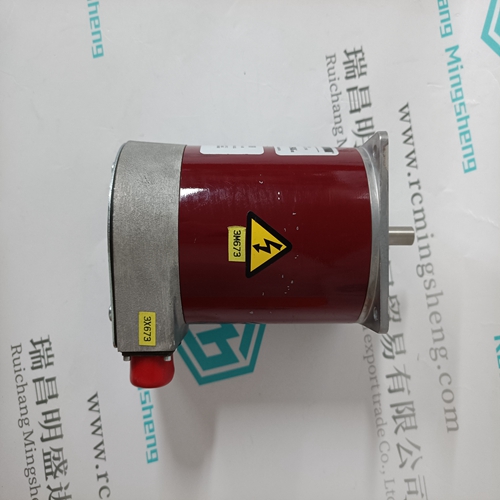
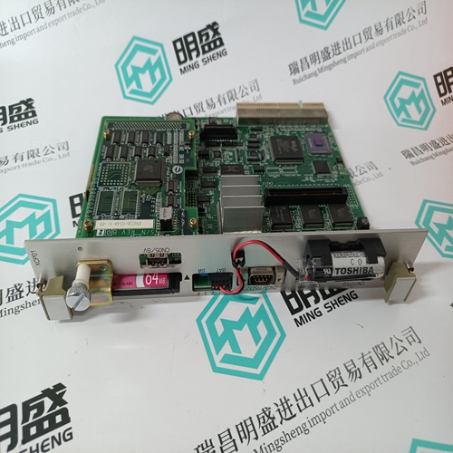
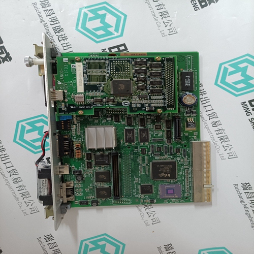
- Product ID: JANCD-XCP01-1
- Brand: YASKAWA
- Place of origin: JAPAN
- Goods status: new/used
- Delivery date: stock
- The quality assurance period: 365 days
- Phone/WhatsApp/WeChat:+86 15270269218
- Email:stodcdcs@gmail.com
- Tags:YASKAWAJANCD-XCP01-1Teaching module
- Get the latest price:Click to consult
The main products
Spare parts spare parts, the DCS control system of PLC system and the robot system spare parts,
Brand advantage: Allen Bradley, BentlyNevada, ABB, Emerson Ovation, Honeywell DCS, Rockwell ICS Triplex, FOXBORO, Schneider PLC, GE Fanuc, Motorola, HIMA, TRICONEX, Prosoft etc. Various kinds of imported industrial parts
Products are widely used in metallurgy, petroleum, glass, aluminum manufacturing, petrochemical industry, coal mine, papermaking, printing, textile printing and dyeing, machinery, electronics, automobile manufacturing, tobacco, plastics machinery, electric power, water conservancy, water treatment/environmental protection, municipal engineering, boiler heating, energy, power transmission and distribution and so on.
YASKAWA JANCD-XCP01-1 Teaching module
● Operating modes of the serial interface The operating mode of the interface has to be set according to the application in each case : – Programming and test or – Man-machine-communication MMC – MODBUS protocol (master and slave) Active mode : The active mode is used for programming and testing the central unit, i.e. it gives the user access to all the programming and test functions of the central unit. Passive mode : The passive mode is used to perform a communication configured with the DRUCK and EMAS blocks between the user program and a device connected to the serial interface. MODBUS protocol : The MODBUS protocol is used to perform a communication between the central unit and a device connected to the serial interface.
– Zero-crossing message (signal changes from 0 to 1 when the counter contents changes from –1 to 0) : - always via the internal variable E 63,13. The zero-crossing message is cancelled when the counter is set. – Fast input of binary signals into the user program with a delay of < 0,02 ms : – Terminal 04 (also designated as E 62,00) : Internal variable E 63,14.
High-speed counter
● Features The high-speed counter used in the central units 07 KR 31 or 07 KT 31 works independently of the user program. Its features are as follows : – The counting frequency is max. 10 kHz. The counter counts the 0–>1 edges at terminal 04 on the plug-in base ECZ (also designated as E 62,00). – The counter counts upwards from –32768 to +32767 (8000H…7FFFH). If +32767 is exceeded, the counter skips to –32768 – Setting the counter in the user program : - to the value contained in the internal word variable AW 06,15 - using the internal variable A 63,15 = 1. NOTE : If the internal variable A 63,15 = 1 is present during several processing cycles, the processor sets the counter at the program end in each case. During the remaining time of the processing cycle, the counter counts pulses at terminal 04. – The counter content can be read via the internal variable EW 06,15.
● Preset start values
You can preset both positive and negative start values for the counter. The counting operation starts at the start value and is continued in correspondence with the arrows in the diagram until the enabling is stopped or a start value is loaded again. ● Negative start value The minimum negative start value is – 32768 (8000H). By presetting a negative start value it is thus possible to count a maximum of 32768 pulses up to the zero crossing of the counter. ● Positive start value If a positive start value is preset, the counter counts up to the value of +32767 (7FFFH), continues the counting operation at the value of –32768 (8000H) and then signals the zero crossing when reaching the transition from –1 to 0. The minimum positive start value is 1. If you preset this value, 65535 pulses will be counted up to the zero crossing. In order to count more than 32767 pulses up to the zero crossing,
Processing times
The most important times for the application of the central units 07 KR 31 / 07 KT 31 with or without connected remote units are : ● The reaction time tkk is the time between a signal transition at the input terminal and the signal response at the output terminal. In case of binary signals, the reaction time consists of the input delay tD, the cycle time tUP of the program processing and the bus transmission time, if the system is expanded by remote units. ● The cycle time tC determines the time intervals after which the processor starts the execution of the user program again. The cycle time has to be specified by the user. It should be greater than the program processing time tUP of the user program, the CS31 bus transmission time and the related waiting times. The cycle time is also the time base for some timecontrolled functions, such as for the timers.