Home > Product > PLC programmable module > YASKAWA JZNC-XIU01B Communication I/o module
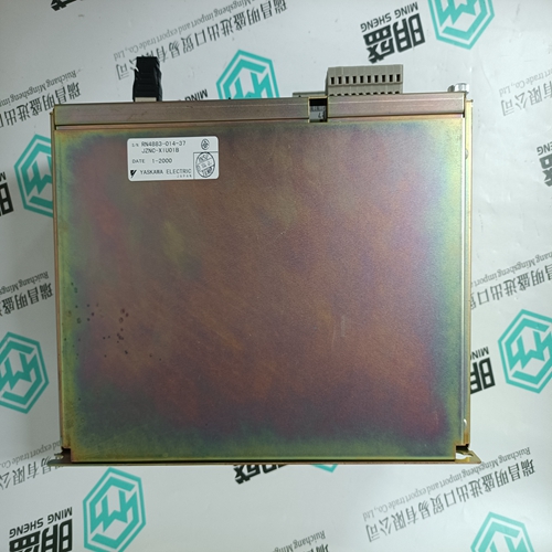
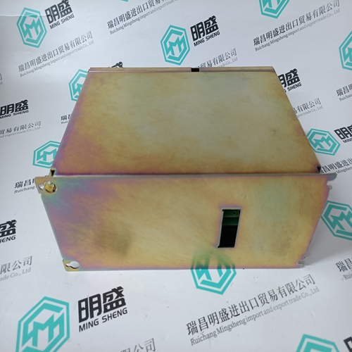
YASKAWA JZNC-XIU01B Communication I/o module
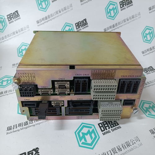
- Product ID: JZNC-XIU01B
- Brand: YASKAWA
- Place of origin: JAPAN
- Goods status: new/used
- Delivery date: stock
- The quality assurance period: 365 days
- Phone/WhatsApp/WeChat:+86 15270269218
- Email:stodcdcs@gmail.com
- Tags:YASKAWAJZNC-XIU01BCommunication I/o module
- Get the latest price:Click to consult
The main products
Spare parts spare parts, the DCS control system of PLC system and the robot system spare parts,
Brand advantage: Allen Bradley, BentlyNevada, ABB, Emerson Ovation, Honeywell DCS, Rockwell ICS Triplex, FOXBORO, Schneider PLC, GE Fanuc, Motorola, HIMA, TRICONEX, Prosoft etc. Various kinds of imported industrial parts
Products are widely used in metallurgy, petroleum, glass, aluminum manufacturing, petrochemical industry, coal mine, papermaking, printing, textile printing and dyeing, machinery, electronics, automobile manufacturing, tobacco, plastics machinery, electric power, water conservancy, water treatment/environmental protection, municipal engineering, boiler heating, energy, power transmission and distribution and so on.
YASKAWA JZNC-XIU01B Communication I/o module
● The program processing time tUP is the net time for processing the user program. For the configuration and for determining the reaction time tkk, the following steps are necessary : – Determining the program processing time tUP – Determining the bus cycle time tb , if there are any remote units connected to the central unit. – Addition of the other times which are within the cycle time tC. – Specification of the cycle time tC. – Reaction time tkk as the sum of the input delay tD and 2 x cycle time tC and output delay tDO. In addition to calculating the cycle time tC in accordance with chapter 5.2 it is possible to measure the capacity utilization on the programmed central unit – with the RUN/ STOP switch set to RUN. The menu item of "Display central unit status" in the programming software 907 PC 331 can be used for this purpose. Increase the cycle time tC until the capacity utilization is below 80 %.
Processing times
The capacity utilization could be greater than 100 %. In this case, a FK3 error is generated (code 200D), M 255,13 is set to 1. The central unit is always processing. This capacity utilization allows to reduce the cycle time even if the initialization is too long.
The cycle time tC has to be preset by the user taking the following equation into consideration : t C ≥ tB + tUP This equation assumes that the processor always gets access in the most unfavourable moment. – For a slave, the bus transmission time is : TB slave = 66 µs + number of sent/received bytes The cycle time tC is stored in KD 00,00 and can be selected in 5 ms time steps. If the selected cycle time is too short, the processor will come in default then. If this lack of time is getting too large over 16 successive cycles, the processor will generate an error (FK3) and continue the program execution (according the value of the system constant KW 00,07).
Using some function blocks
such as the PI controller, the error-free execution depends on an exact timing sequence. Make sure that there is a larger time reserve. The correct setting of the cycle time can be checked by the following procedure : – Loading the user program into the central unit. – If the operating mode has been switched over from stand-alone to bus master : Power ON or menu item "Enable PLC mode" in the programming software. – Interrogation of the capacity utilization using the menu item of "Display PLC status". – Changing the cycle time tC until the capacity utilization is below 80 %.
● The maximum reaction time tkk (input terminal to output terminal) results from the asynchronicity of the operations.
Without regard to the address ranges
the following units can be connected to a CS31 system bus : – max. 1 bus master – max. 31 remote units/slaves Further restrictions result from the address range of the central units : 07 KR 31/07 KT 31: – max. 28 analog input units; 07 KR 91/07 KT 92/07 KT 93 : - max. 12 analog input units – max. 12 analog output units - max. 12 analog output units – max. 31 binary input units - max. 31 binary input units – max. 31 binary output units - max. 31 binary output units There may be further restrictions according to the structure of the installation and the type of remote units. For the recommended addresses, (see chapter 6.1"Recommended unit adresses on the CS31 bus").