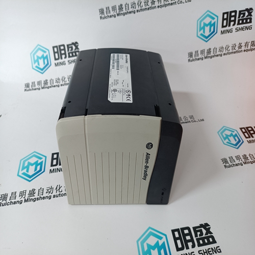
Home > Product > DCS control system > HONEYWELL CC-MCAR01 Switch power supply module
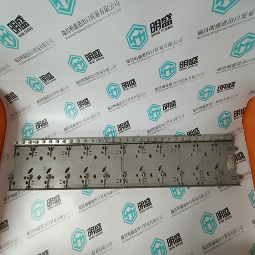
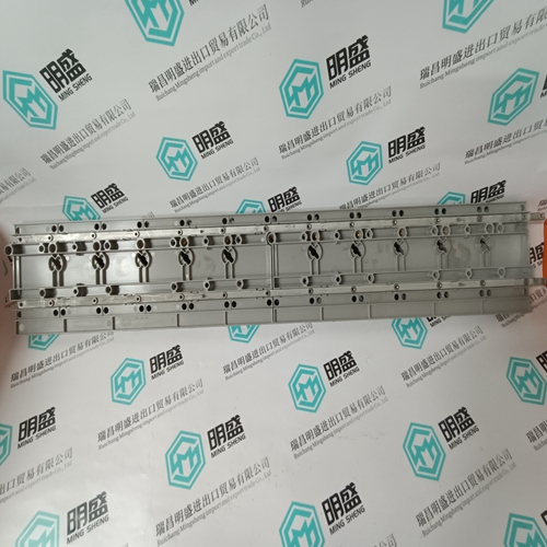
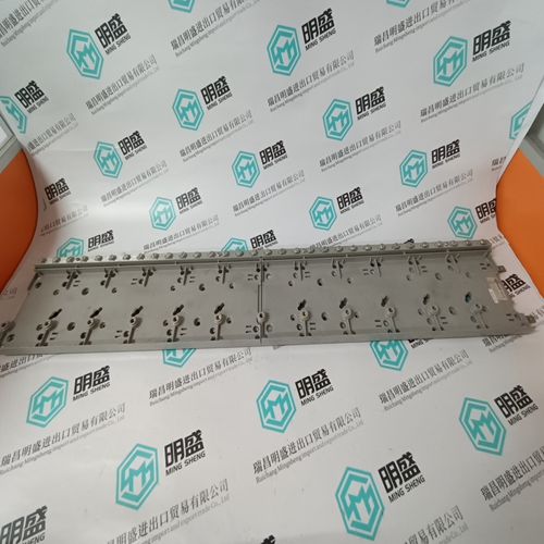
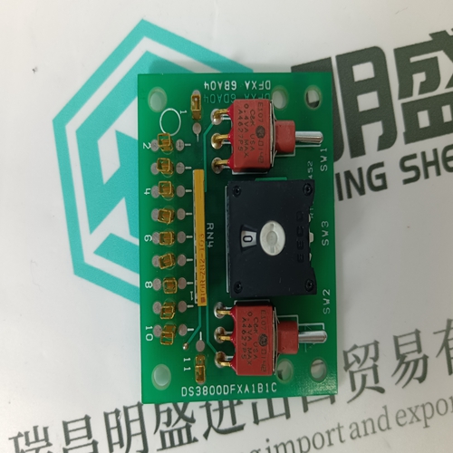
HONEYWELL CC-MCAR01 Switch power supply module
- Product ID: CC-MCAR01
- Brand: HONEYWELL
- Place of origin: The United States
- Goods status: new/used
- Delivery date: stock
- The quality assurance period: 365 days
- Phone/WhatsApp/WeChat:+86 15270269218
- Email:stodcdcs@gmail.com
- Tags:HONEYWELLCC-MCAR01Switch power supply module
- Get the latest price:Click to consult
The main products
Spare parts spare parts, the DCS control system of PLC system and the robot system spare parts,
Brand advantage: Allen Bradley, BentlyNevada, ABB, Emerson Ovation, Honeywell DCS, Rockwell ICS Triplex, FOXBORO, Schneider PLC, GE Fanuc, Motorola, HIMA, TRICONEX, Prosoft etc. Various kinds of imported industrial parts
Products are widely used in metallurgy, petroleum, glass, aluminum manufacturing, petrochemical industry, coal mine, papermaking, printing, textile printing and dyeing, machinery, electronics, automobile manufacturing, tobacco, plastics machinery, electric power, water conservancy, water treatment/environmental protection, municipal engineering, boiler heating, energy, power transmission and distribution and so on.
HONEYWELL CC-MCAR01 Switch power supply module
Structure of the input and output addresses in the remote units The binary input unit ICSI 08 D1 will be explained here as an example. The bus master central unit reads the input signals as operands. The complete address of an input signal has the following structure : E 10 ,05 Channel number of the input, here : input 05 Unit address (group number) here : unit address 10 choosen by the DIL switch on the plug-in base ECZ (see vol. 2). Operand identifier, here : binary input
purpose of : – simplifying and schematizing the setting of addresses on the CS31 system bus – simplifying diagnosis and troubleshooting. The standard addressing makes sure that there will be no address overlapping even for units with a bigger amount of data.
Recommendations
● Assign a specific unit address for each unit/each slave central unit; binary and analog units can be set to the same address. ● Unit addresses for binary remote units and central units : 0, 2…, 58, 60 (all even numbers), (see also chapter 6.5 "Intelligent I/O remote units (slave central units")). ● Unit addresses for analog remote unit : 0…5 and 8...15 : analog input remote units 0…5 : analog output remote units. ● Address switch No. 8 on the plug-in base ECZ always set to OFF (≤ 7) for the binary remote units.
● Input and output units connected as slaves to the CS31 system bus The remote units are mounted on the plug-in base ECZ. This plug-in base is equipped with an address switch (DIP switch) for setting the unit address. The combination of unit type, unit address and channel number results in the variable address used by the bus master central unit. ● Setting the address switch for binary units The possible range of unit addresses when using the central units 07 KR 31 / 07 KT 31 is : – 0…61
stand-alone central unit
If the central units 07 KR 31 / 07 KT 31 are used without
the CS31 system bus connected, perform the following
setting when programming in the user program :
System constant KW 00,00 = –2
This value is the factory setting If remote units (slaves) are connected to the central unit
07 KR 31 or 07 KT 31 via the CS31 system bus, proceed
as follows :
1. Change the system constant : KW 00,00 = –1
2. Save the user program in the EEPROM.
3. Activate the new PLC mode by :
– calling the menu item "Enable PLC mode" in the
ABB programming and test system, or
– entering the command WARM
The central units 07 KR 31, 07 KT 31, 07 KR 91, 07 KT 92 and 07 KT 93 can also be used as slaves at the CS31 system bus, (see chapter 6 "Addressing" example 3). The central units 07 KR 31 / 07 KT 31 / 07 KR 91 / 07 KT 92 / 07 KT 93 may be used both in the binary range and in the word range.
The address
can be set to a value from 0 to 61. The
maximum permissible address depends on the size of the
set transmit and receive range. The larger you choose the
transmit or the receive range, the smaller is the maximum
permissible address (see examples 1…3).
If you want to switch over to the "slave mode", proceed as
follows :
1. Change the system constant : KW 00,00 = 0…61
Only for 07 KR 31 and 07 KT 31 : if KW 00,00 = 100, the
address of the slave is choosen by the dil switches of the
plug-in base ECZ as a standard remote unit address
range : 0…61.
2. Save the user program in the EEPROM.
3. Activate the new PLC mode by :
– calling the menu item "Enable PLC mode" in the ABB
programming and test system or
– entering the command WARM
