Home > Product > Gas turbine system > IS200DSPXH1DBC Gas turbine module
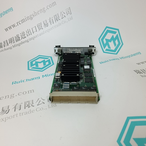
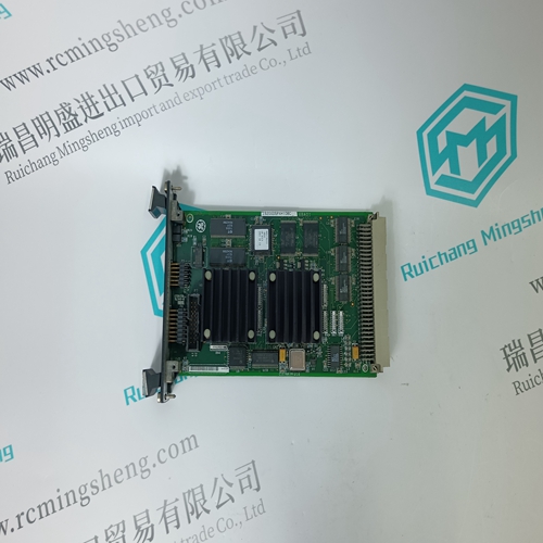
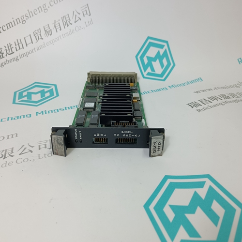
IS200DSPXH1DBC Gas turbine module
- Product ID: IS200DSPXH1DBC
- Brand: GE
- Place of origin: the United States
- Goods status: new/used
- Delivery date: stock
- The quality assurance period: 365 days
- Phone/WhatsApp/WeChat:+86 15270269218
- Email:stodcdcs@gmail.com
- Tags:IS200DSPXH1DBCGas turbine module
- Get the latest price:Click to consult
The main products
Spare parts spare parts, the DCS control system of PLC system and the robot system spare parts,
Brand advantage: Allen Bradley, BentlyNevada, ABB, Emerson Ovation, Honeywell DCS, Rockwell ICS Triplex, FOXBORO, Schneider PLC, GE Fanuc, Motorola, HIMA, TRICONEX, Prosoft etc. Various kinds of imported industrial parts
IS200DSPXH1DBC Gas turbine module
The enable input terminal block of the braking chopper is at a dangerously high voltage when the chopper is connected to the ACS 600 with the mains power applied. Dangerous voltages from external control circuits may be present inside the ACS 600 even when its mains power is shut off.More Warnings and Notes are printed at appropriate instances along the text. The General Safety Instructions given in the Installation and Start-up Manual of the ACS 600 frequency converter should be studied before attempting any work on or with the unit.
The Guide is intended for the people responsible for installing, commissioning and servicing the braking chopper of an ACS 600 product family frequency converter. The user is expected to have a basic knowledge of electrical fundamentals, electrical wiring practices and ACS 600 family frequency converters.
What This Guide Contains
Safety Instructions are placed on the first few pages of the Guide. Safety Instructions describe the formats for various warnings and notations used in this guide. This chapter also states the General Safety Instructions. Chapter 1 – Introduction to This Guide contains a description of this Guide. Chapter 2 – Overview contains a short description of resistor braking, braking choppers and braking resistors. The standard braking chopper and braking resistor available for each ACS 600 type are given in the rating tables. Chapter 3 – Voltage Selection and Mechanical Installation describes how to set the chopper voltage level and install the chopper. Chapter 4 – Electrical Installation contains instructions for power cable selection and routing, control connections, and power connections. Chapter 5 – Fault Tracing contains information on chopper and resistor fault indications, and fault tracing. Appendix A contains the dimensional drawings of the braking choppers and braking resistors to be installed outside the ACS 600 housing. Appendix B contains the calculation instructions for the maximum allowed braking power. Related Publications The Installation and Start-up Manual and the Programming Manual of the frequency converter.