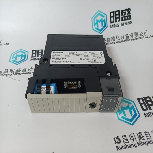
Home > Product > Gas turbine system > VMIVME-7750-746001 gas turbine electric card
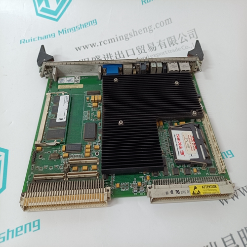
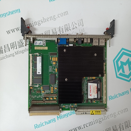
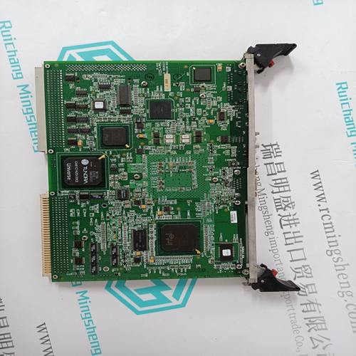
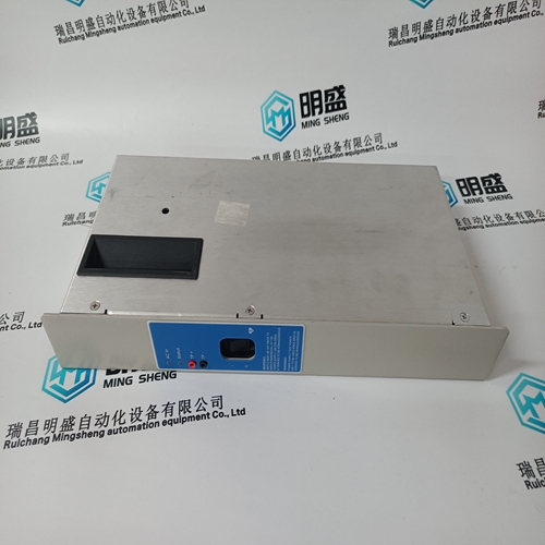
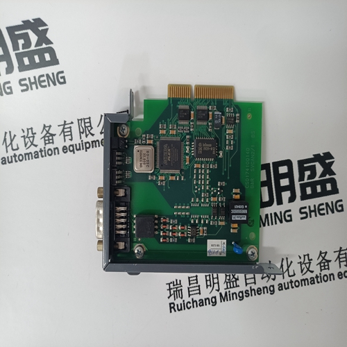
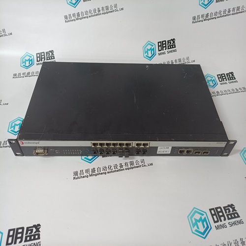
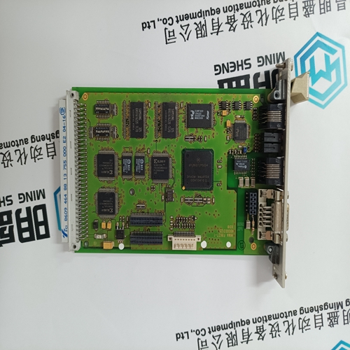
VMIVME-7750-746001 gas turbine electric card
- Product ID: VMIVME-7750-746001
- Brand: GE
- Place of origin: the United States
- Goods status: new/used
- Delivery date: stock
- The quality assurance period: 365 days
- Phone/WhatsApp/WeChat:+86 15270269218
- Email:stodcdcs@gmail.com
- Tags:VMIVME-7750-746001gas turbine electric card
- Get the latest price:Click to consult
The main products
Spare parts spare parts, the DCS control system of PLC system and the robot system spare parts,
Brand advantage: Allen Bradley, BentlyNevada, ABB, Emerson Ovation, Honeywell DCS, Rockwell ICS Triplex, FOXBORO, Schneider PLC, GE Fanuc, Motorola, HIMA, TRICONEX, Prosoft etc. Various kinds of imported industrial parts
Products are widely used in metallurgy, petroleum, glass, aluminum manufacturing, petrochemical industry, coal mine, papermaking, printing, textile printing and dyeing, machinery, electronics, automobile manufacturing, tobacco, plastics machinery, electric power, water conservancy, water treatment/environmental protection, municipal engineering, boiler heating, energy, power transmission and distribution and so on.
VMIVME-7750-746001 gas turbine electric card
Use as normal input signal: The signal is available in the user program in the operand E 62,00. The signal delay time is 7 ms. The updating of the operand E 62,00 is performed before the start of each program cycle. – Use as high-speed input signal: The signal is available in the user program in the operand E 63,14. The signal delay time is 8 ms. The updating of the operand E 63,14 is performed before the start of each program cycle. In the Dual Port RAM (DPR) this signal is updated after each CS31 bus telegram. With the aid of the function block WOL this signal can be read in the Dual Port RAM (word address C000:1FEH, Bit 14). – Use for the high-speed counter: The signal is used as counting input (50 kHz) for the high-speed counter.
Use as normal input signal: The signal is available in the user program in the operand E 62,01. The signal delay time is 7 ms. The updating of the operand E 62,01 is performed before the start of each program cycle. – Use as high-speed input signal: The signal is available in the user program in the operand E 63,15. The signal delay time is 8 ms. The updating of the operand E 63,15 is performed before the start of each program cycle. In the Dual Port RAM (DPR) this signal is updated after each CS31 bus telegram. With the aid of the function block WOL this signal can be read in the Dual Port RAM (word address C000:1FEH, Bit 15). – Use for the high-speed counter: The signal is used as enable input for the high-speed counter.
Connection of the analog inputs
with signal ranges either 0...10 V, 0...5 V or 0...20 mA The following illustration shows the circuit configuration of the analog inputs of the first channel as an example. Features: – The 4 analog inputs are not separated electrically. – The A/D converter has a resolution of 12 bits. – The analog inputs are able to evaluate the following signal ranges each as required: 0...10 V resolution ca. 2.5 mV 0... 5 V resolution ca. 1.25 mV 0...20 mA resolution ca. 5 µA – Resolution in the PLC: The smallest detectable changes on the analog side (2.5 mV, 1.25 mV, 5 µA) cause the numerical value in the PLC program to be changed by the amount of 8. – Relationship between the analog value at the analog input and the numerical value in the PLC program: selected range numerical values 0...10 V 0...32760D or 0000...7FF8H 0... 5 V 0...32760D or 0000...7FF8H 0...20 mA 0...32760D or 0000...7FF8H For further information see volume 2, chapter 5.1 General information on using the analog input and output modules. For 07 KT 92 ”Assignment b” is valid.
Connection of the binary outputs
The following illustration shows the circuit configuration of the binary outputs. Features of the outputs: – The 8 outputs are arranged in one group and are electrically connected with each other. – The outputs can be loaded with a rated current of 500 mA. – The group as a whole is electrically isolated from the rest of the device. – The outputs use transistors and are short-circuit-proof. – The eight transistors of the group have a common power supply. – The outputs are automatically switched off in case of overload or short-circuit.
