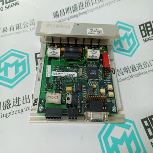
Home > Product > Servo control system > Kollmorgen E33NCHA-LNN-NS-00 drive
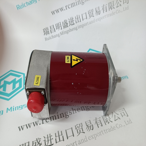
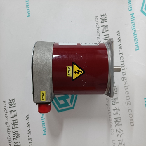
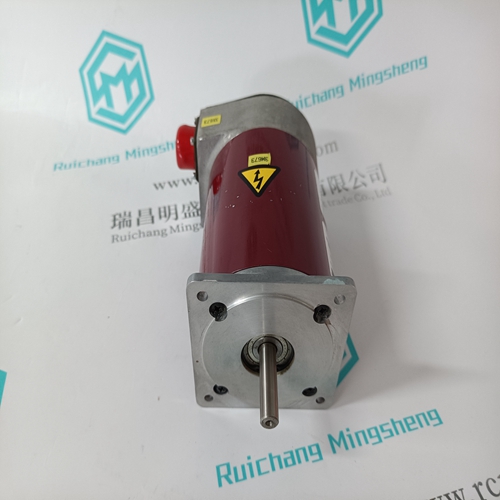
Kollmorgen E33NCHA-LNN-NS-00 drive
- Product ID: E33NCHA-LNN-NS-00
- Brand: KOLLMORGEN
- Place of origin: the United States
- Goods status: new/used
- Delivery date: stock
- The quality assurance period: 365 days
- Phone/WhatsApp/WeChat:+86 15270269218
- Email:stodcdcs@gmail.com
- Tags:KollmorgenE33NCHA-LNN-NS-00drive
- Get the latest price:Click to consult
The main products
Spare parts spare parts, the DCS control system of PLC system and the robot system spare parts,
Brand advantage: Allen Bradley, BentlyNevada, ABB, Emerson Ovation, Honeywell DCS, Rockwell ICS Triplex, FOXBORO, Schneider PLC, GE Fanuc, Motorola, HIMA, TRICONEX, Prosoft etc. Various kinds of imported industrial parts
Products are widely used in metallurgy, petroleum, glass, aluminum manufacturing, petrochemical industry, coal mine, papermaking, printing, textile printing and dyeing, machinery, electronics, automobile manufacturing, tobacco, plastics machinery, electric power, water conservancy, water treatment/environmental protection, municipal engineering, boiler heating, energy, power transmission and distribution and so on.
Kollmorgen E33NCHA-LNN-NS-00 drive
Configuration steps: PLC program 1) Activate terminals 03 and 41 – The terminals 03 and 41 are activated using the operand A 63,14. IL (instruction list): ! K 00,01 = A 63,14 (with K 00,01 = 1) 2) Preset start value for the counter The start value (AW 06,15) is set to the value of –180. The counter will then count starting from –180 in positive direction. The transition from –1 to 0 will be signalled. IL (instruction list): ! KW 01,00 = AW 06,15 (with KW 01,00 = –180) 3) Adopt start value into the counter After each counting operation, the start value is immediately set again into the counter by means of the ”zero crossing” signal (E 63,13). Operand A 63,15 = 1 has to be set for this purpose. At program start, the start value is loaded once into the counter by means of the initialization flag M 255,15 (M 255,15 has the value of 0 after program start).
Preset start values
You can preset both positive and negative start values for the counter. The counting operation starts at the start value and is continued in correspondence with the arrows in the diagram until the enabling is stopped or a start value is loaded again. Negative start value The minimum negative start value is –32768 (8000H). By presetting a negative start value it is thus possible to count a maximum of 32768 pulses up to the zero crossing of the counter. Positive start value If a positive start value is preset, the counter counts up to the value of +32767 (7FFFH), continues the counting operation at the value of–32768 (8000H) and then signals the zero crossing when reaching the transition from –1 to 0. The minimum positive start value is 1. If you preset this value, 65535 pulses will be counted up to the zero crossing. In order to count more than 32767 pulses up to the zero crossing, the start value has to be calculated according to the following equation: Start value = 32767 – (number of pulses – 32768) Example: 40 000 pulses are to be counted. The start value is in the positive range, because more than 32768 pulses have to be counted.
Concerning the Setting up of Installations
Apart from the basic ”Regulations for the Setting up of Power Installations” DIN VDE* 0100 and for ”The Rating of Creepage Distances and Clearances” DIN VDE 0110 Part 1 and Part 2 the regulations ”The Equipment of Power Installations with Electrical Components” DIN VDE 0160 in conjunction with DIN VDE 0660 Part 500 have to be taken into due consideration. Further attention has to be paid to DIN VDE 0113 Part 1 and Part 200 in case of the control of working and processing machines. If operating elements are to be mounted near parts with dangerous contact voltage DIN VDE 0106 Part 100 is additionally relevant. If the protection against direct contact according to DIN VDE 0160 is required, this has to be ensured by the user (e.g. by incorporating the elements in a switch-gear cabinet). The devices are designed for pollution severity 2 in accordance with DIN VDE 0110 Part 1. If higher pollution is expected, the devices must be installed in appropriate housings. The user has to guarantee that the devices and the components belonging to them are mounted following these regulations. For operating the machines and installations, other national and international relevant regulations, concerning prevention of accidents and using technical working means, also have to be met.
The ABB Procontic devices
are designed according to IEC 1131 Part 2. Meeting this regulation, they are classified in overvoltage category II which is in conformance with DIN VDE 0110 Part 2. For the direct connection of ABB Procontic devices, which are powered with or coupled to AC line voltages of overvoltage category III, appropriate protection measures corresponding to overvoltage category II according to IEC–Report 664/1980 and DIN VDE 0110 Part 1 are to install. Equivalent standards: DIN VDE 0110 Part 1 IEC 664 DIN VDE 0113 Part 1 EN 60204 Part 1 DIN VDE 0660 Part 500 EN 60439–1 IEC 439–1
