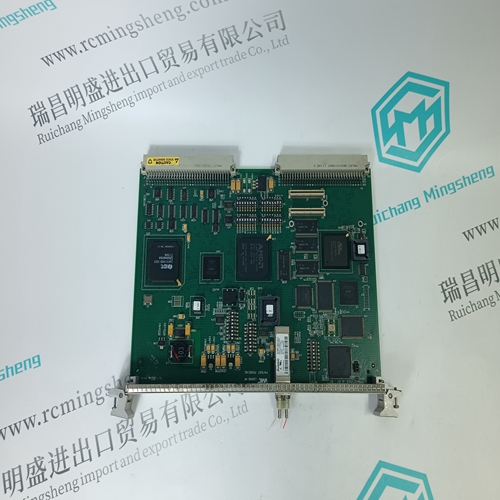
Home > Product > Gas turbine system > IS200ERDDH1ABA Gas turbine card
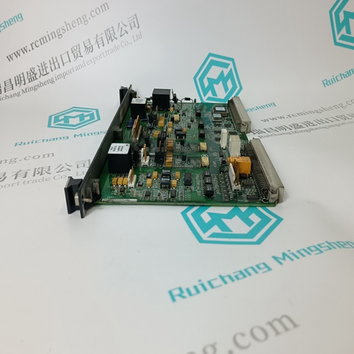
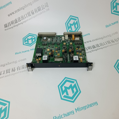
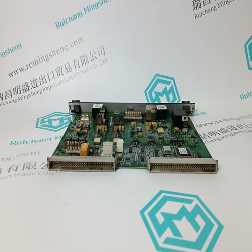
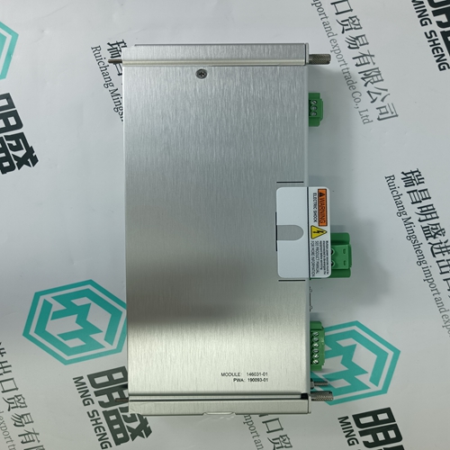
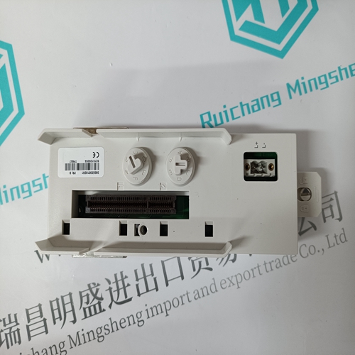
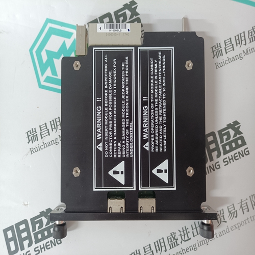
IS200ERDDH1ABA Gas turbine card
- Product ID: IS200ERDDH1ABA
- Brand: GE
- Place of origin: the United States
- Goods status: new/used
- Delivery date: stock
- The quality assurance period: 365 days
- Phone/WhatsApp/WeChat:+86 15270269218
- Email:stodcdcs@gmail.com
- Tags:IS200ERDDH1ABAGas turbine card
- Get the latest price:Click to consult
The main products
Spare parts spare parts, the DCS control system of PLC system and the robot system spare parts,
Brand advantage: Allen Bradley, BentlyNevada, ABB, Emerson Ovation, Honeywell DCS, Rockwell ICS Triplex, FOXBORO, Schneider PLC, GE Fanuc, Motorola, HIMA, TRICONEX, Prosoft etc. Various kinds of imported industrial parts
IS200ERDDH1ABA Gas turbine card
The NBRA-658, NBRA-659 and NBRA-669 require the use of braking circuit fuses. Other units do not require the fuses if all of the following provisions are fulfilled: • the ACS 600 mains cable is protected with fuses • the cable and the fuses are of the type specified for that particular converter model in its Installation and Start-up Manual • the braking chopper circuit cables are as specified in this Guide. The fuses in the braking circuit protect the chopper and the braking circuit cables in a cable short-circuit situation. The fuses do not protect the cables, the chopper or the resistor against overload. Overload protection can be implemented by wiring the temperature sensor of the resistor to the Enable Input of the chopper and simultaneously connecting the Relay Output of the chopper to the main contactor control circuit of the ACS 600. The fuses must be installed as near as possible to the ACS 600 intermediate circuit terminals (UDC+ and UDC–). Unprotected cable length must not exceed 0.5 metres. Rating Tables The standard braking choppers, braking resistors, cables and fuses are specified in Tables 2-1 and 2-2. (See also Chapter 4 – Electrical Installation.)
The Maximum Braking Power of the ACS 600 / NBRA-6xx combination is given for a reference braking cycle (the drive brakes for one minute every ten minutes). If the actual cycle does not correspond to the reference cycle, the maximum allowed braking power must be calculated. See Appendix B – Maximum Braking Power for instructions.
Resistance value
for the listed resistor type. Note: This is also the minimum allowed resistance value for the braking resistor. ER Energy pulse that the resistor assembly will withstand (400 s duty cycle). This energy will heat the resistor element from 40 °C to the maximum allowable temperature. PRcont Continuous power (heat) dissipation of the resistor when placed correctly. Energy ER dissipates in 400 seconds. A Conductor cross-sectional areas for the copper cable to be used for connecting the braking resistor and the chopper (or the chopper and the ACS 600). The cable should have a concentric conductor (screen). The standard cables with three-phase conductors and a concentric conductor are given. A two-conductor screened cable may also be used if available. PBRmax Maximum braking power of the ACS 600 equipped with the standard chopper and the standard resistor. The drive and the chopper will withstand this braking power for one minute every ten minutes. Note: The braking energy transmitted to the resistor during any period shorter than 400 seconds may not exceed ER. * The SACE04RE40 resistor consists of four resistor elements connected in parallel. The resistance of one element is 160 ohm. The SACE15RE13 resistor consists of four resistor elements connected in parallel. The resistance of one element is 52 ohm. The SACE15RE22 resistor consists of four resistor elements connected in parallel. The resistance of one element is 88 ohm. The SAFUR resistors consist of several resistor elements. The resistance of one element is 8 ohm. The NBRA-653 and -663 are to be installed outside the converter module. Their degree of protection is IP54. The NBRA-654, -655, -656, -657, -664, -666 and -667 are to be installed inside the converter module. The NBRA-658, -659 and -669 are to be installed outside the converter module. Their degree of protection is IP00. All braking resistors are to be installed outside the converter module. The SACE braking resistors are built in an IP21 metal housing. The SAFUR braking resistors are built in an IP00 metal frame.
