Home > Product > DCS control system > CI626A 3BSE005029R1 Control module
CI626A 3BSE005029R1 Control module
- Product ID: CI626A 3BSE005029R1
- Brand: ABB
- Place of origin: The Swiss
- Goods status: new/used
- Delivery date: stock
- The quality assurance period: 365 days
- Phone/WhatsApp/WeChat:+86 15270269218
- Email:stodcdcs@gmail.com
- Tags:CI626A 3BSE005029R1Control module
- Get the latest price:Click to consult
The main products
Spare parts spare parts, the DCS control system of PLC system and the robot system spare parts,
Brand advantage: Allen Bradley, BentlyNevada, ABB, Emerson Ovation, Honeywell DCS, Rockwell ICS Triplex, FOXBORO, Schneider PLC, GE Fanuc, Motorola, HIMA, TRICONEX, Prosoft etc. Various kinds of imported industrial parts
Products are widely used in metallurgy, petroleum, glass, aluminum manufacturing, petrochemical industry, coal mine, papermaking, printing, textile printing and dyeing, machinery, electronics, automobile manufacturing, tobacco, plastics machinery, electric power, water conservancy, water treatment/environmental protection, municipal engineering, boiler heating, energy, power transmission and distribution and so on.
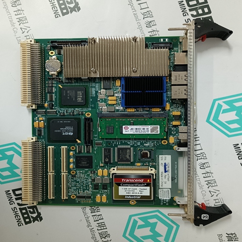
CI626A 3BSE005029R1 Control module
The networking interface, a special parallel interface, allows the 07 KP 92 communication module to be connected to ABB Procontic CS31 central units (such as 07 KR 91 R151, 07 KT 92, 07 KT 93). The housing of the communication module is connected to the housing of the ABB Procontic CS31 basic unit by a snap–fit connection. The electrical connection is via a 40–pole ribbon cable with socket connector, soldered onto the 07 KP 92 side.
Mounting the expansion housing 1. Detach the cover on unit 07 KT 93 from the networking interface. 2. Plug the socket strip of the 40–pole ribbon cable secured to the 07 KP 92 onto the networking connector of the 07 KT 93. 3. Place both units on a level surface and slide them together so that they engage. 4. Slide in the connection part to fix the housing in position. Note: Mounting of the 07 KP 92 to 07 KR 91 / 07 KT 92 takes place in a similar way
Freely configurable LED displays
The green LED ”RUN” lights up when the user application is being processed. The red LED ”ERR” lights up when a fatal error (RAM error, DP–RAM error, EPROM error, Flash EPROM error) or a serious error is present.Programming and test software 907 KP 92 The communication module is programmed with the programming and test software 907 KP 92. This software can be run on an IBM–compatible PC. The PC can be connected to either interface COM3 or COM4 of the communication module. In addition to the programming and test software, the package 907 KP 92 contains documentation of the communication module 07 KP 92, the CE library and configuration examples.
Technical data In general, the details in Section 1 ”System data and system structure” of volume 2 of the system description ”ABB Procontic CS31” apply as technical data. Supplementary and deviating data is listed below. 1.6.1 General data Number of serial interfaces 2 Number of parallel interfaces 1 networking interface for connecting to the ABB Procontic CS31 central unit Built–in application software memory Flash EPROM 32 kbytes Diagnosis 4 configurable LEDs: LED1...4 (control led by the application program) Operating and error displays 3 LEDs: RUN, ERR, Supply Conductor cross section for the max. 2.5 mm2 removable terminals
Connection serial interface COM3, COM4
Interface standard EIA RS–232 or EIA RS–422 or EIA RS–485 Programming with 907 KP 92 via IBM–PC (or compatible) Man–machine communication yes, e.g. via ABB Procontic operating station 35 BS 40 Electrical isolation yes, interfaces with respect to each other and with respect to the rest of the unit (also see Figure 5) Potential differences So that no earthing potential differences arise between the 07 KP 92 and the peripheral units connected to COM3 and COM4, the latter are supplied from the switch cabinet mains socket (also see earthing connections in Figure 5).
in accordance with DIN EN 50022–35, 15 mm deep The DIN rail is located in the middle between the upper and the lower edges of the module. Fastening by screws using 4 M4 screws. Width x height x depth 140 x 120 x 85 mm Wiring method by removeable terminal blocks with screw–type terminals, max. 2.5 mm2 Weight 450 g Dimensions for mounting see the following drawing