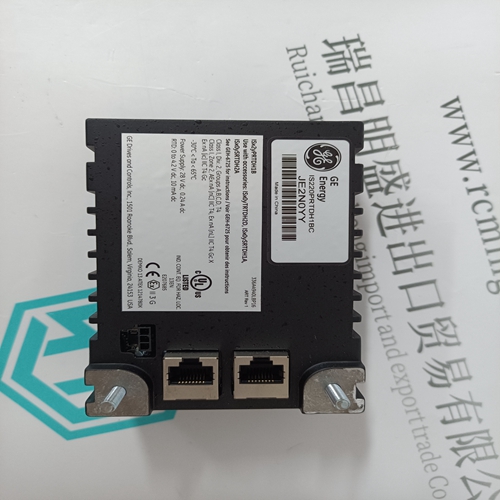
Home > Product > Robot control system > STAHL ET-436-AT-R2-HB-TX-100GB-V Man-machine interface module
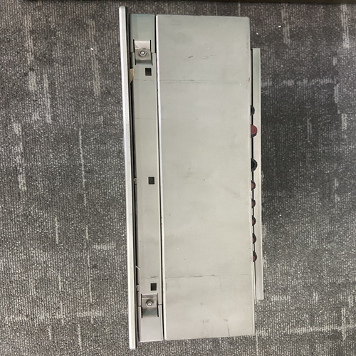
STAHL ET-436-AT-R2-HB-TX-100GB-V Man-machine interface module
- Product ID: ET-436-AT-R2-HB-TX-100GB-V
- Brand: STAHL
- Place of origin: the United States
- Goods status: new/used
- Delivery date: stock
- The quality assurance period: 365 days
- Phone/WhatsApp/WeChat:+86 15270269218
- Email:stodcdcs@gmail.com
- Tags:STAHLET-436-AT-R2-HB-TX-100GB-VMan-machine interface module
- Get the latest price:Click to consult
The main products
Spare parts spare parts, the DCS control system of PLC system and the robot system spare parts,
Brand advantage: Allen Bradley, BentlyNevada, ABB, Emerson Ovation, Honeywell DCS, Rockwell ICS Triplex, FOXBORO, Schneider PLC, GE Fanuc, Motorola, HIMA, TRICONEX, Prosoft etc. Various kinds of imported industrial parts
Products are widely used in metallurgy, petroleum, glass, aluminum manufacturing, petrochemical industry, coal mine, papermaking, printing, textile printing and dyeing, machinery, electronics, automobile manufacturing, tobacco, plastics machinery, electric power, water conservancy, water treatment/environmental protection, municipal engineering, boiler heating, energy, power transmission and distribution and so on.
STAHL ET-436-AT-R2-HB-TX-100GB-V Man-machine interface module
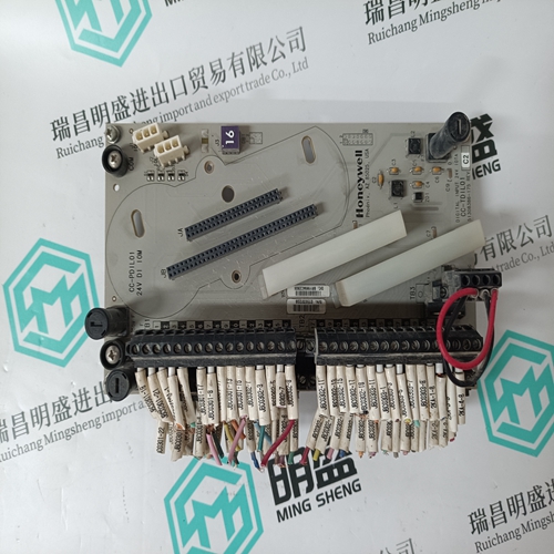
Grounding The block’s mounting screws must not be used as the only means of grounding the block. Connect the green ground screw on the block to a reliable ground system using a short wire lead, minimum size AWG #12 (avg 3.3mm2 in cross-section). Warning If mounting screws do not make good ground connection and the ground screw is not connected to a reliable ground, the block is not grounded. Electrical shock hazard exists. Death or personal injury may result. Removing an Electronics Assembly The block’s Electronics Assembly can be replaced with a compatible model without removing field wiring or reconfiguring the block.
Unscrew the retaining screws at the top and bottom of the block. 2. Using a Block Puller (IC660BLM507), engage the tabs in the first vent slots. Move the tool to the center of the block and squeeze the handle. 3. Pull the Electronics Assembly upward. Warning If power is applied to the field terminals, power is also exposed on the connector pins at the base of the Terminal Assembly, and electrical shock hazard exists. Do not touch the connector pins! Death or injury may result. Inserting an Electronics Assembly 1. Align the Electronics Assembly in the guides and push down firmly.
Block Wiring
All terminals accept one AWG #12 wire (avg 3.3mm2 cross-section) or two AWG #14 wires (each avg 2.1mm2 in cross-section). The minimum recommended wire size is AWG #22 (avg .36mm2 in cross-section). Block terminals can also accommodate spade or ring terminals up to 0.27 inch (6.85mm) wide with a minimum opening for a #6 screw, and up to 0.20 inch (5.1mm) depth from the screw center to the back barrier. Be sure unshielded wire ends are not longer than 2 inches (5 cm). Do not overtorque the terminal screws. Recommended torque for all terminals is 6 in/lb (.678 N/M). Serial Bus Wiring Using one of the cable types recommended in the System and Communications User’s Manual, connect the serial bus to terminals 1- 4. (If a Bus Switching Module will be connected directly to the block, see below instead).
Power Connections
Connect a DC power source to the DC+ terminal (5) and the return to the DC- terminal (22). Depending on the layout and current loads, positive and negative connections can be bussed and made by individual wires back to the block or power source. Power Disconnects It is important to wire block power disconnects so that block power and input power will be removed at the same time. Locate the power disconnect as shown below.If circuit power is not removed at the same time as block power, the block may power up when multiple inputs are activated, even though one leg of power has been removed from the block. Connections for a DC Source Block Any circuit can be an input or output. Connect one terminal of the device to the block (terminals 6-21). Connect outputs to DC- and inputs to DC+. No logic inversion is needed.
If any input is configured as a Tristate Input, install a resistor across the dry contacts of the input device. This added resistance is required to use the Open Wire diagnostic. The LED will glow dimly as a result.