Home > Product > Robot control system > DYNAPAR HR62506000001 CPU module
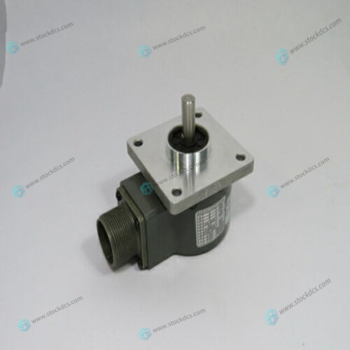
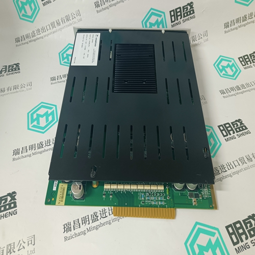
DYNAPAR HR62506000001 CPU module
- Product ID: HR62506000001
- Brand: DYNAPAR
- Place of origin: The United States
- Goods status: new/used
- Delivery date: stock
- The quality assurance period: 365 days
- Phone/WhatsApp/WeChat:+86 15270269218
- Email:stodcdcs@gmail.com
- Tags:DYNAPARHR62506000001CPU module
- Get the latest price:Click to consult
DYNAPAR HR62506000001 CPU module
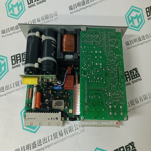
With the flag spring and printed circuit board carrying the miniature relay assembled to the top and bottom plates check the settings: – lift the flat spring to the latched position so that the tab on the flag spring rests on the catch on the relay. a. with a gap of 0.4mm between the inside face of the armature and the core, the flag should remain latched. b. with a gap of 0.15mm the flag should drop. If necessary, carefully bend the tab to fulfil these conditions.

 Warranty: 365 days Goods status: new/used Shipping method: Courier delivery

Company product range
----------------------Ruichang Mingsheng Automation Equipment Co., Ltd----------------------
PLC module, programmable controller, CPU module, IO module, DO module, AI module, DI module
Network communication module,
Ethernet module, motion control module, analog input module, analog output module, digital input module, digital output
Module, redundancy module, power module, relay output module, relay input module, processor module
These tests should be performed by positioning
an appropriate feeler gauge between the armature and coil and then energising the coil with the appropriate voltage to pick up the relay. – with the flag in the latched position the spring should exert a force of 10 – 12 grams on the catch. This is checked using a gram gauge, just lifting the flag off the catch. – with the flag in the latched position the white stripes on the flag should show evenly through the slots in the nameplate. Adjustment is made by slackening the pcb fixing screws and moving the pcb assembly up or down as necessary, then retightening the screws. After adjustment of the pcb the catch engagement must be rechecked as in a. and b. above
This article from the temporal Ming sheng automation equipment co., LTD., reproduced please attach this link: http://www.stockdcs.com/
