Home > Product > DCS control system > DSSR122 4899001-NK Control module
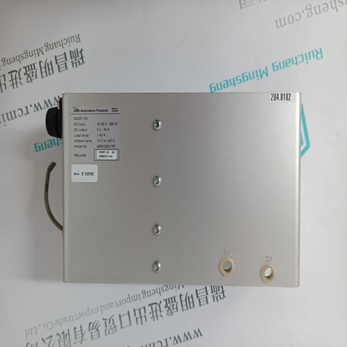
DSSR122 4899001-NK Control module
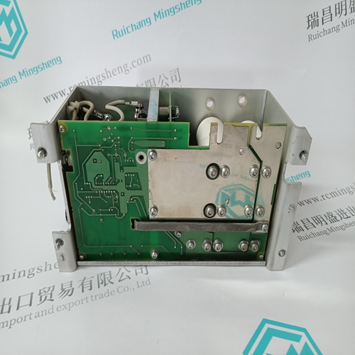
- Product ID: DSSR122 4899001-NK
- Brand: ABB
- Place of origin: The Swiss
- Goods status: new/used
- Delivery date: stock
- The quality assurance period: 365 days
- Phone/WhatsApp/WeChat:+86 15270269218
- Email:stodcdcs@gmail.com
- Tags:DSSR122 4899001-NKControl module
- Get the latest price:Click to consult
The main products
Spare parts spare parts, the DCS control system of PLC system and the robot system spare parts,
Brand advantage: Allen Bradley, BentlyNevada, ABB, Emerson Ovation, Honeywell DCS, Rockwell ICS Triplex, FOXBORO, Schneider PLC, GE Fanuc, Motorola, HIMA, TRICONEX, Prosoft etc. Various kinds of imported industrial parts
Products are widely used in metallurgy, petroleum, glass, aluminum manufacturing, petrochemical industry, coal mine, papermaking, printing, textile printing and dyeing, machinery, electronics, automobile manufacturing, tobacco, plastics machinery, electric power, water conservancy, water treatment/environmental protection, municipal engineering, boiler heating, energy, power transmission and distribution and so on.
DSSR122 4899001-NK Control module
Transmit Enable Jumper (JP2) The transmit enable jumper JP2 controls whether the card can transmit on the network. To enable transmission, put the jumper on the two pins. To disable transmission, remove the jumper. For normal operation, the transmitter should be enabled. Use this feature if you are using the card for passive monitoring of the network and to ensure that you do not go active on the network. 2.5.2 Flash Write Enable Jumper (JP4) The flash write enable jumper JP4 controls writing to flash memory on the card. To disable writing to flash, remove the jumper from the card or put it on just one of the pins for storage. If the jumper is removed, the current contents of flash memory cannot be overwritten. Use this feature if you have a software module and configuration in flash and you want to prevent anyone from accidentally overwriting the software module or configuration.
Boot Protect Jumper (JP9)
The 5136-PFB-VME contains a short bootstrap program in flash memory which is written at the factory and does not normally need to be overwritten. The boot protect jumper JP9 controls whether you can overwrite the contents of this boot program. If the jumper is installed, the contents of the boot loader are protected and cannot be overwritten. If the jumper is removed, you can overwrite the boot loader. If the boot program becomes corrupted, the card must be returned to the factory to be reinitialized. 2.5.4 Byte Order of Addresses and Data Byte ordering of addresses and data is always an issue with VME computers. The processor on the card is an Intel i960. It stores data in low byte-high byte order. Depending on the type of host system, you may have to do swapping of addresses and data in order to access data correctly
Starting the Card
Before using the 5136-PFB-VME card on ProfiBus, download the PFBPROFI software module to the card, and configure and run the software module. Download the software module into shared memory from the host or into flash memory using the serial CONFIG port on the card. The module for shared memory is called vmeprofi.ss1. The module for flash memory is called vmeprofi.ssf. To run a software module, load the appropriate Initial Boot Record to the card (IBR, refer to section 2.7.3, Initial Boot Record). There are two IBRs, one to run a module from flash and another to run a module from shared memory. It is possible to have one module in flash and a different one in shared memory and to run one or the other depending on which IBR you use. When you first receive the card, the only software on the card is a short bootstrap startup program in flash. Use this bootstrap program to access the card and download a software module to the card through the serial port.
The 5136-PFB-VME distribution contains two versions of the include file that describes the structure of the data on the card. Profictl.h shows the structures for the module in an unswapped environment and profiswp.h shows the structures for the module in a swapped environment. The addresses in this manual are the addresses as seen by the processor on the card.
If you are reading or writing words, the address must be even and you must swap bytes of data. If you are reading or writing a byte, you must use the alternate byte address within the word. For example to read from address 0, use address 1 and to read from address 1, use address 0.