Home > Product > DCS control system > TRICONEX AI2351 communication card
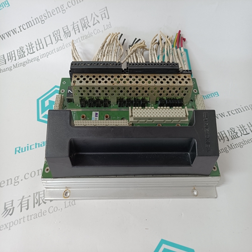
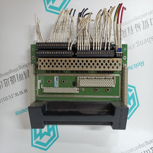
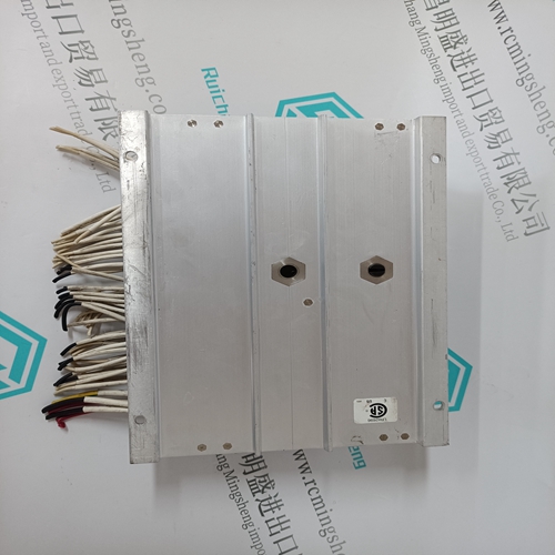
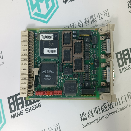
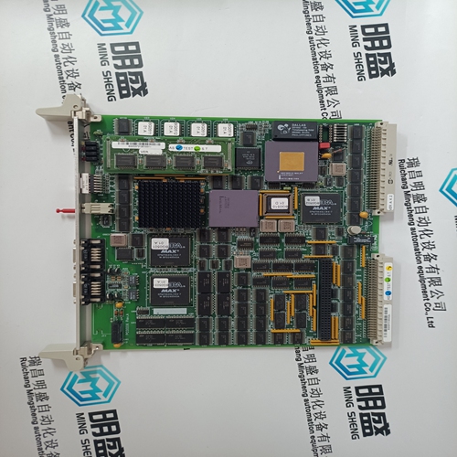
TRICONEX AI2351 communication card
- Product ID: AI2351
- Brand: TRICONEX
- Place of origin: The United States
- Goods status: new/used
- Delivery date: stock
- The quality assurance period: 365 days
- Phone/WhatsApp/WeChat:+86 15270269218
- Email:stodcdcs@gmail.com
- Tags:TRICONEX AI2351communication card
- Get the latest price:Click to consult
The main products
Spare parts spare parts, the DCS control system of PLC system and the robot system spare parts,
Brand advantage: Allen Bradley, BentlyNevada, ABB, Emerson Ovation, Honeywell DCS, Rockwell ICS Triplex, FOXBORO, Schneider PLC, GE Fanuc, Motorola, HIMA, TRICONEX, Prosoft etc. Various kinds of imported industrial parts
Products are widely used in metallurgy, petroleum, glass, aluminum manufacturing, petrochemical industry, coal mine, papermaking, printing, textile printing and dyeing, machinery, electronics, automobile manufacturing, tobacco, plastics machinery, electric power, water conservancy, water treatment/environmental protection, municipal engineering, boiler heating, energy, power transmission and distribution and so on.
TRICONEX AI2351 communication card
The [COMMANDS] section of the configuration file sets the Modbus master port command list. This list polls Modbus slave devices attached to the Modbus master port. The module supports numerous commands. This permits the module to interface with a wide variety of Modbus protocol devices. The command list is formatted differently than the other sections of the configuration file. Commands are present in a block between the labels START and END. These labels inform the program where the list resides. The module's program will parse all commands after the START label until it reaches the END label or until the command count entered for the port is reached. The function codes used for each command are those specified in the Modbus protocol. Each command list record has the same format. The first part of the record contains the information relating to the MVI94-MCM, communication module and the second part contains information required to interface to the Modbus slave device.
Enable Code
This field defines whether the command is to be executed and under what conditions. If the parameter is set to 0, the command is disabled and will not be executed in the normal polling sequence. The command can be executed under the control of the processor using a Command Control block. Setting the parameter to a value of 1 for the command causes the command to be executed each scan of the command list if the Poll Interval Time is set to zero. If the Poll Interval time is set, the command will be executed, when the interval timer expires. If the parameter is set to 2, the command will execute only if the internal data associated with the command changes. This value is valid only for write commands. If the parameter is set to 3, it will function in the same manner as an enable code of 1except that the floating-point is disabled for this command. A parameter value of 4 is the same as a parameter value of 2 but with floating-point handling disabled for the command.
Internal Address
This field specifies the virtual Modbus database register to be associated with the command. If the command is a read function, the data read from the slave device will be placed starting at the register value entered in this field. If the command is a write function, the data written to the slave device will be sourced from the address specified. Register addresses specified for commands must reside in the range specified by the Maximum Register parameter under the [MODBUS MASTER] section. 3.6.3 Poll Interval Time This parameter specifies the minimum interval to execute continuous commands (Enable code of 1). The parameter is entered in units of seconds. Therefore, if a value of 10 is entered for a command, the command will execute no more frequently than every 10 seconds. 3.6.4 Count This parameter specifies the number of registers or digital points to be associated with the command. Functions 5 and 6 ignore this field as they only apply to a single data point. For functions 1, 2 and 15, this parameter sets the number of digital points (inputs or coils) to be associated with the command. For functions 3, 4 and 16, this parameter sets the number of registers to be associated with the command.
