Home > Product > DCS control system > YOKOGAWA ALR121-S00 Communication module
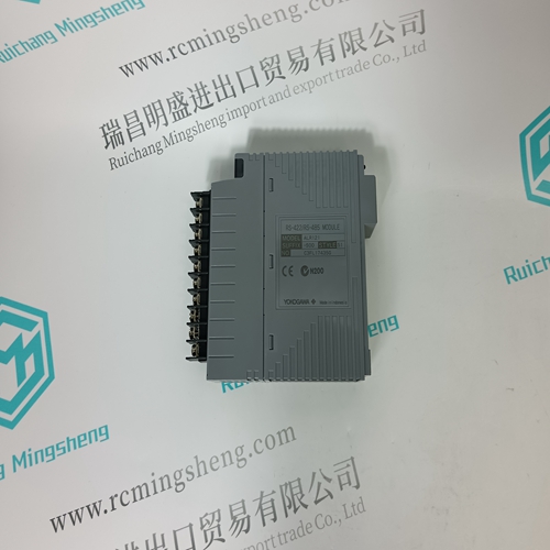
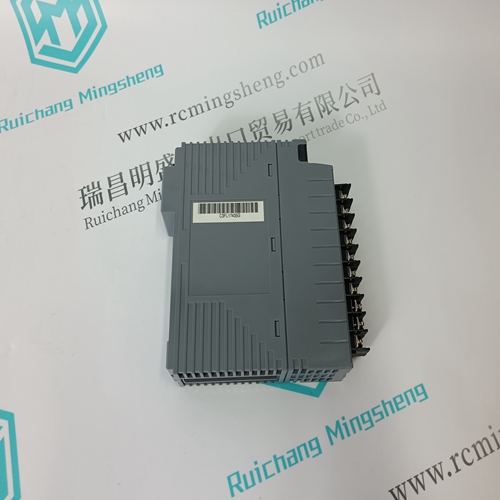
YOKOGAWA ALR121-S00 Communication module
- Product ID: YOKOGAWA
- Brand: ALR121-S00
- Place of origin: Japan
- Goods status: new/used
- Delivery date: stock
- The quality assurance period: 365 days
- Phone/WhatsApp/WeChat:+86 15270269218
- Email:stodcdcs@gmail.com
- Tags:YOKOGAWA ALR121-S00Communication module
- Get the latest price:Click to consult
The main products
Spare parts spare parts, the DCS control system of PLC system and the robot system spare parts,
Brand advantage: Allen Bradley, BentlyNevada, ABB, Emerson Ovation, Honeywell DCS, Rockwell ICS Triplex, FOXBORO, Schneider PLC, GE Fanuc, Motorola, HIMA, TRICONEX, Prosoft etc. Various kinds of imported industrial parts
YOKOGAWA ALR121-S00 Communication module
This chapter contains instructions for electrical installation. • Power cable selection and routing (for all chopper types) are described on this page. • The control connections (for all chopper types) are described on pages 4-2 to 4-4. • The power connections are described on pages 4-5 to 4-16. The installation instructions are given separately for each chopper. Note: Drive Parameter 20.5 (20.7 for ACP 600) OVERVOLTAGE CTRL must be set to OFF to enable chopper operation. Power Cable Selection and Routing Standard screened three-conductor and single-conductor power cables are specified in Tables 2-1 and 2-2. Two-conductor screened cables can also be used. Under the converter, chopper and resistor units, provide adequate support for the cables. The following should be considered in order to minimise electromagnetic interference caused by the rapid current changes in the cables: – The braking power line should be completely screened, either by cable screen or metallic enclosure. Unscreened single-core cable can only be used if routed inside a cabinet that efficiently suppresses the radiated RFI emissions.
Control Connections
– The cables should be installed away from other cable routes. – Long parallel runs with other cables should be avoided. The minimum parallel cabling separation distance should be 0.3 metres. – Cables should cross at right angles. The maximum lengths of the chopper and resistor cables are 5 m and 10 m respectively. The longer the cables, the higher the inductive load. High load inductance causes voltage peaks over the semiconductors of the chopper.
The chopper control connections are shown below. The chopper is also operational without the control connections.
*The NBRA-658, NBRA-659 and NBRA-669 are equipped with an internal temperature sensitive switch. In these units, NBRC terminal block X2 is wired via this switch to a separate terminal block (X1), shown in the NBRA-658/659/669 t° 1 2 dimensional drawing.