Home > Product > DCS control system > TRICONEX DI3301 Communication module
TRICONEX DI3301 Communication module
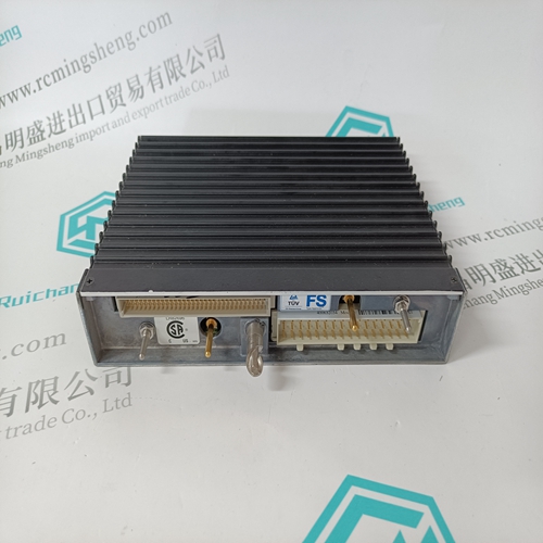
- Product ID: DI3301
- Brand: TRICONEX
- Place of origin: The United States
- Goods status: new/used
- Delivery date: stock
- The quality assurance period: 365 days
- Phone/WhatsApp/WeChat:+86 15270269218
- Email:stodcdcs@gmail.com
- Tags:TRICONEX DI3301Communication module
- Get the latest price:Click to consult
The main products
Spare parts spare parts, the DCS control system of PLC system and the robot system spare parts,
Brand advantage: Allen Bradley, BentlyNevada, ABB, Emerson Ovation, Honeywell DCS, Rockwell ICS Triplex, FOXBORO, Schneider PLC, GE Fanuc, Motorola, HIMA, TRICONEX, Prosoft etc. Various kinds of imported industrial parts
Products are widely used in metallurgy, petroleum, glass, aluminum manufacturing, petrochemical industry, coal mine, papermaking, printing, textile printing and dyeing, machinery, electronics, automobile manufacturing, tobacco, plastics machinery, electric power, water conservancy, water treatment/environmental protection, municipal engineering, boiler heating, energy, power transmission and distribution and so on.
TRICONEX DI3301 Communication module
Now you have everything that shows up on the HyperTerminal screen being
logged to a file called ProSoft.txt. This is the file that you will then be able to
email to ProSoft Technical Support to assist with issues on the communications
network.
To begin the display of the communications data, you will then want to press [B]
to tell the module to start printing the communications traffic out on the debug
port of the module.The
Database View Menu
Press [D] from the Main menu to open the Database View menu. Use this menu command to view the current contents of the module database. Press [?] to view a list of commands available on this menu.The module error/status data areas are discussed in this section. The module contains three areas related to this data. The user defines the location of two of these data sets in the virtual Modbus database of the module. The error/status data contains module data, the command error list data set contains the errors associated with the command list and the slave status list contains the current communication status of each slave on the master port.
Error and Status Data Table
The error/status data table is located at the virtual Modbus address assigned by the user. If the address is set to -1 or the frequency parameter is set to 0, the data will not be placed in the database. It will only be available through the Configuration/Debug Port. If valid address and frequency values are assigned, the module will update the Modbus data area. The data area will be initialized with zeros whenever the processor is initialized. This occurs during a cold-start (power-on), reset (reset push-button pressed) or a warm-boot operation (commanded or loading of new configuration). The data area is a 22-word register block. The structure of the block is shown in the following table.