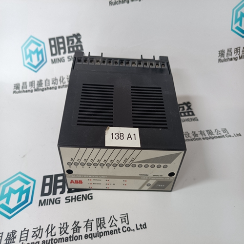
Home > Product > DCS control system > TRICONEX DO2401 base module
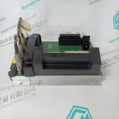
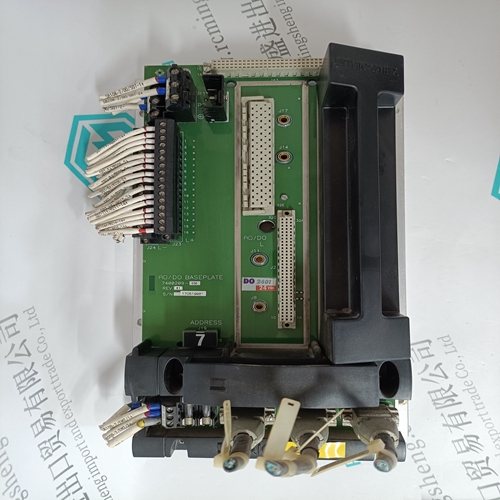
TRICONEX DO2401 base module
- Product ID: DO2401
- Brand: TRICONEX
- Place of origin: The United States
- Goods status: new/used
- Delivery date: stock
- The quality assurance period: 365 days
- Phone/WhatsApp/WeChat:+86 15270269218
- Email:stodcdcs@gmail.com
- Tags:TRICONEX DO2401base module
- Get the latest price:Click to consult
The main products
Spare parts spare parts, the DCS control system of PLC system and the robot system spare parts,
Brand advantage: Allen Bradley, BentlyNevada, ABB, Emerson Ovation, Honeywell DCS, Rockwell ICS Triplex, FOXBORO, Schneider PLC, GE Fanuc, Motorola, HIMA, TRICONEX, Prosoft etc. Various kinds of imported industrial parts
Products are widely used in metallurgy, petroleum, glass, aluminum manufacturing, petrochemical industry, coal mine, papermaking, printing, textile printing and dyeing, machinery, electronics, automobile manufacturing, tobacco, plastics machinery, electric power, water conservancy, water treatment/environmental protection, municipal engineering, boiler heating, energy, power transmission and distribution and so on.
TRICONEX DO2401 base module
Each command in the command list has a reserved word value for a status/error code. This error data list can be read using the Configuration/Debug Port. Additionally, the data can be placed in the virtual Modbus database of the module. The configuration parameter "Command Error Pointer" defines the register address in the virtual Modbus database where the data will be placed. The first word in the register location defined contains the status/error code for the first command in the port's command list. Each successive word in the command error list is associated with the next command in the list. Therefore, the size of the data area is dependent upon the number of commands defined. Refer to the following Error Codes section to interpret the status/error codes present in the data area.
Slave Status List
The slave status list views the communication status of each slave device on a master port. Slaves attached to the master port can have one of the following states Slaves are defined to the system when the module initializes the master command list. Each slave defined will be set to a state of 1 in this initial step. If the master port fails to communicate with a slave device (retry count expired on a command), the master will set the state of the slave to a value of 2 in the status table. This suspends communication with the slave device for a user specified scan count (Error Delay Count value in the configuration). Each time a command in the list is scanned that has the address of a suspended slave, the delay counter value will be decremented. When the value reaches zero, the slave state will be set to one. This will enable polling of the slave. The slave status list can only be viewed using the module’s configuration/debug port. The 'O' option on the main menu displays the status of all 256 slave units.
LED Definition
This section defines the indications provided on the MVI94-MCM module through LEDs. A description of each LED is provided in the following topics. 4.5.1 PRT1 This LED indicates data transmit and receive activity on the configuration port. When the TXD or RXD pin is active on the port, the LED will illuminate green. When the port is not active, the LED remains in the off state. 4.5.2 U1 This LED indicates backplane data transfer operation. When the module is successfully writing data to the FLEX I/O backplane, the LED will be in the off state. When the module is reading a new block of data from the FLEX I/O backplane, the LED will be in the on state (amber). During normal operation of the module, this LED should turn on and off at a vary rapid rate. If the LED never turns on, check your ladder logic to verify that the data transfer is set up correctly. 4.5.3 U2 This LED indicates communication errors on the Modbus master port. The LED is illuminated (amber) when no error exists on the port. If a communication error is recognized on the port, the LED will turn off. If the LED is off, check for errors in the command list to determine the error condition recognized by the module.
