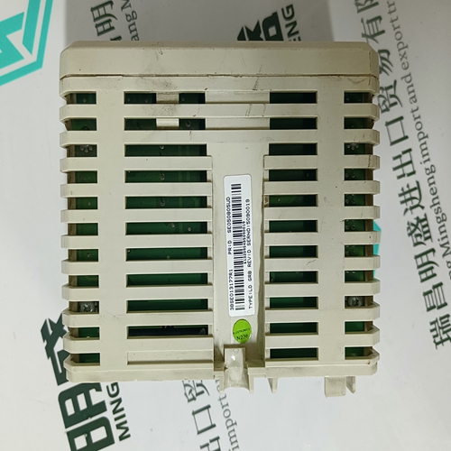
Home > Product > Servo control system > DANAHER S21260-SRS Servo driver module
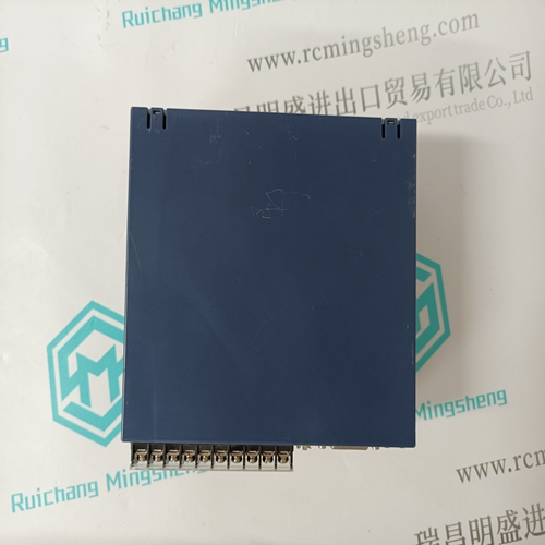
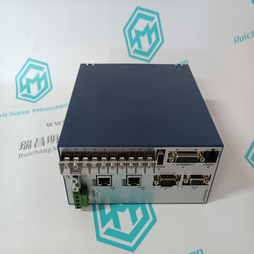
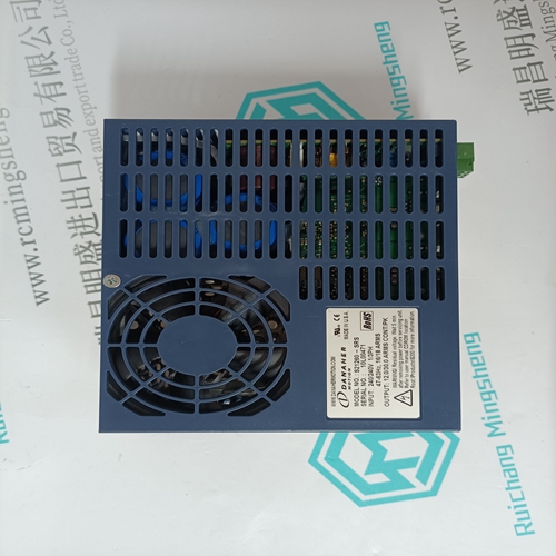
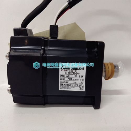
DANAHER S21260-SRS Servo driver module
- Product ID: S21260-SRS
- Brand: DANAHER
- Place of origin: the United States
- Goods status: new/used
- Delivery date: stock
- The quality assurance period: 365 days
- Phone/WhatsApp/WeChat:+86 15270269218
- Email:stodcdcs@gmail.com
- Tags:DANAHERS21260-SRSServo driver module
- Get the latest price:Click to consult
The main products
Spare parts spare parts, the DCS control system of PLC system and the robot system spare parts,
Brand advantage: Allen Bradley, BentlyNevada, ABB, Emerson Ovation, Honeywell DCS, Rockwell ICS Triplex, FOXBORO, Schneider PLC, GE Fanuc, Motorola, HIMA, TRICONEX, Prosoft etc. Various kinds of imported industrial parts
Products are widely used in metallurgy, petroleum, glass, aluminum manufacturing, petrochemical industry, coal mine, papermaking, printing, textile printing and dyeing, machinery, electronics, automobile manufacturing, tobacco, plastics machinery, electric power, water conservancy, water treatment/environmental protection, municipal engineering, boiler heating, energy, power transmission and distribution and so on.
DANAHER S21260-SRS Servo driver module
The steps outlined in the diagram above are discussed below: 1 During program initialization, the write and read block identification codes are set to one. The last block read variable is set to zero. 2 The program copies the first six-word block of the virtual Modbus database starting at the user defined BT Read Start Register to the input image (words 2 to 7). It then sets the current read block code in word 1 of the input image. To "trigger" the write operation, the program places the current write block code into word 0 of the input image. 3 The Flex processor recognizes a new value in word 0 of the input image (based on the last_read_block_code not equal to read_block_code) in its ladder logic. The ladder logic computes the offset into the file based on the following formula:4 The new data contained in the input image (words 2 to 7) is copied to the offset in the processor’s user data file. The last_read_block_code storage register in the processor is updated with the new read_block_code.
Reference User Manual
Data is transferred between the processor and the module using the block identification codes of 1 to 666 and 9956 to 9958 and 9960. The other block codes control the module from the processors ladder logic. They are implemented when the ladder logic needs to control the module. In order to use one of the blocks, the ladder logic inserts the data and code in the output image of the module. The data should be set before the code is placed in the block. This operation should be performed after the receipt of a new write block from the module. A discussion of each set of codes is given in the following topics. Event Blocks (1000 to 1255) These control blocks are sent from the processor to the module to execute a Modbus command out the Modbus master port. It should be used for commands that are not found in the command list. Use blocks 1000 to 1255 to execute commands in the list under processor control. The format for this block is shown in the following table.
Block Request from Processor to Module
The data contained in the block is used by the module to construct a valid Modbus command and defines what data in the virtual Modbus database to use with the command. These parameters are the same as defined for the command list. Refer to the Commands section of the documentation for more information. When the module receives a block 1000 to 1255, it will check the command queue for an available position. If there is space in the command queue, the module will construct a command and place it in the queue. The module will respond with the following block in the input image after processing request.
The ladder logic can examine word 2 of the input image to determine if the module was able to execute the command. If invalid parameters are set in the event request block, the command may still be placed in the queue and there will be no error indication. Command Blocks (2001 to 2006) These control blocks are sent from the processor to the module to execute one or more commands in the module's command list out the Modbus master port. Commands selected for execution need not have the Enable Code set (1 or 2) but must be valid commands. The format for this block is shown in the following table
