Home > Product > DCS control system > YOKOGAWA CP461-50 Communication module
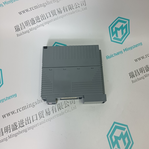
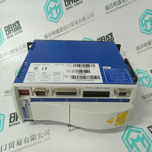
YOKOGAWA CP461-50 Communication module
- Product ID: CP461-50
- Brand: YOKOGAWA
- Place of origin: Japan
- Goods status: new/used
- Delivery date: stock
- The quality assurance period: 365 days
- Phone/WhatsApp/WeChat:+86 15270269218
- Email:stodcdcs@gmail.com
- Tags:YOKOGAWA CP461-50Communication module
- Get the latest price:Click to consult
The main products
Spare parts spare parts, the DCS control system of PLC system and the robot system spare parts,
Brand advantage: Allen Bradley, BentlyNevada, ABB, Emerson Ovation, Honeywell DCS, Rockwell ICS Triplex, FOXBORO, Schneider PLC, GE Fanuc, Motorola, HIMA, TRICONEX, Prosoft etc. Various kinds of imported industrial parts
YOKOGAWA CP461-50 Communication module
The use of the relay output for controlling the main contactor of the ACS 600 is highly recommended (see page 4-3). The enable input and the fibre optic connection are optional (see page 4-4). The terminals for the control connections are on the chopper control board (NBRC), located inside the chopper housing. The front plate of the chopper must be removed to access the terminals. WARNING! Before starting the installation work inside the ACS 600: Switch off the ACS 600 power supply. Wait for five minutes to ensure that the intermediate circuit is discharged. Switch off dangerous voltages connected from external circuits to the digital inputs and to the relay outputs of the ACS 600. WARNING! Do not touch the printed circuits. They are extremely sensitive to electrostatic discharge.
WARNING! In a chopper failure, always switch off the power supply to the ACS 600. This is the only way to guarantee safe operation in case of a chopper failure since the chopper is unable to disconnect the resistor from the intermediate circuit.
Relay Output
The relay output indicates chopper faults. The changeover switch opens when a failure is detected or the chopper is unpowered.
It is highly recommended that the ACS 600 be equipped with a main contactor and a manual control switch (or switches). See Figure 4-2 below for connection examples.
Enable Input By default, the Enable input terminal block X2 (X1 on NBRA-658/659/ 669) is short-circuited with a jumper connection, and the enable signal is present all the time. The signal can be given externally by connecting a break contact to the terminal block as shown in Figure 4-1. When the contact opens (enable signal is switched off), the chopper stops operating, and its relay output gives a fault indication. The NBRA-658, NBRA-659 and NBRA-669 are equipped with an internal temperature sensitive switch. In these units, NBRC terminal block (Enable input) is wired via this switch to a separate terminal block (X1), shown in the dimensional drawing.