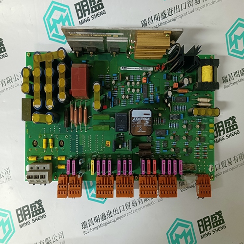
Home > Product > DCS control system > HONEYWELL 51305896-200 NIM MODEM module
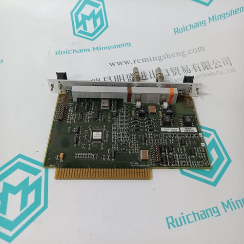
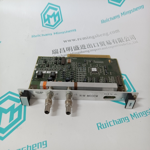
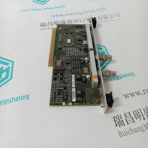
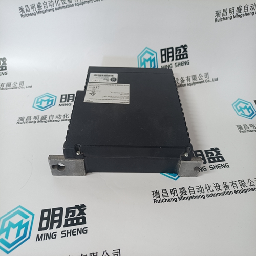
HONEYWELL 51305896-200 NIM MODEM module
- Product ID: 51305896-200 NIM MODEM
- Brand: HONEYWELL
- Place of origin: The United States
- Goods status: new/used
- Delivery date: stock
- The quality assurance period: 365 days
- Phone/WhatsApp/WeChat:+86 15270269218
- Email:stodcdcs@gmail.com
- Tags:HONEYWELL51305896-200 NIM MODEMmodule
- Get the latest price:Click to consult
The main products
Spare parts spare parts, the DCS control system of PLC system and the robot system spare parts,
Brand advantage: Allen Bradley, BentlyNevada, ABB, Emerson Ovation, Honeywell DCS, Rockwell ICS Triplex, FOXBORO, Schneider PLC, GE Fanuc, Motorola, HIMA, TRICONEX, Prosoft etc. Various kinds of imported industrial parts
Products are widely used in metallurgy, petroleum, glass, aluminum manufacturing, petrochemical industry, coal mine, papermaking, printing, textile printing and dyeing, machinery, electronics, automobile manufacturing, tobacco, plastics machinery, electric power, water conservancy, water treatment/environmental protection, municipal engineering, boiler heating, energy, power transmission and distribution and so on.
HONEYWELL 51305896-200 NIM MODEM module
The I/O modules can be inserted into any I/O location in the 800 series I/O structure. The module slides easily into the module housing and does not interfere with any other module’s operation. Shielded Design The module’s protective case shields the logic circuitry from any electrical interference and minimizes the possibility of any noise being coupled from the user side of the circuitry to adjacent modules. A ground is automatically established when the module is inserted into the housing. This low impedance earth ground originates from the housing’s backplane.When used with a PLC in a remote configuration, the appropriate RIO Adapter module or RIO Adapter module with ASCII, must be present in the I/O rack. (See instructions shipped with the adapter modules.)NOTE: The active indicator does not represent the condition of the I/O points. The indicator may be lit with one or more of the I/O points not working properly
I/O Map Overview
The I/O map is used to direct the flow of data between the various I/O modules and the logic program. It is the tie between the references used in the logic program and the I/O module connection points. 800 Series Configuration The 800 series I/O map lets you match the controller I/O addresses with what will be installed or with what actually exists in the field. The I/O map also tells the controller how to use an input signal in user logic, and, where to send an output signal. The format of register data (BCD - binary coded decimal or BIN binary) is specified on this screen. The screen objective is to load the card selections and reference number selections to complete the I/O configuration.
Adhere to the following guidelines for grounding the 800 series I/O modules: z To have proper case ground, the housing must be connected to earth ground. z When using shielded field circuit wires, do not ground the shield at both ends of the circuit (i.e., the module and the field device). z Single point grounding should be used where possible. Priority for shield grounding is as follows: z Field side device case, if metal. z Earth ground, as close to the field side device or module as possible. z From shield to frame.
Installation Overview
Installation of the 800 series module involves unpacking the module, wiring the field connector, installing key pins in the housing, and mounting the module in its housing.Terminals accept either two 141 AWG size wires or one 12 AWG size wire/point. NOTE: Neat and proper workmanship methods by qualified personnel must be employed when making connections to this module. Take extra precautions when using stranded wire. Ensure that loose or projecting strands do not short circuit or ground the other terminals. The use of solid wire is recommended.When performing this step, refer to Appendix A for illustrations of optional key pin patterns for the 800 Series module to be installed. Appendix A contains key pin patterns for all 800 series I/O modules.
When using key pins (provided with housing shipment), install them above and below housing slot selected for installation of module. The following illustration shows this optional mechanical keying system used to match the module type with a particular slot in the housing to ensure proper module replacement.
