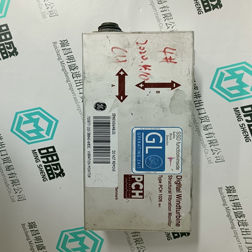
Home > Product > DCS control system > HONEYWELL 51401583-100 EPNI Digital card
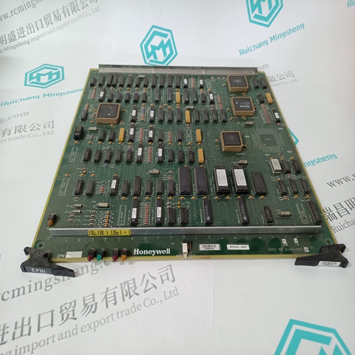
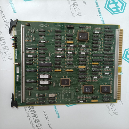
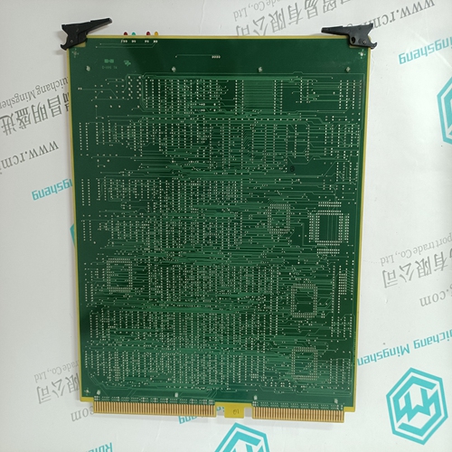
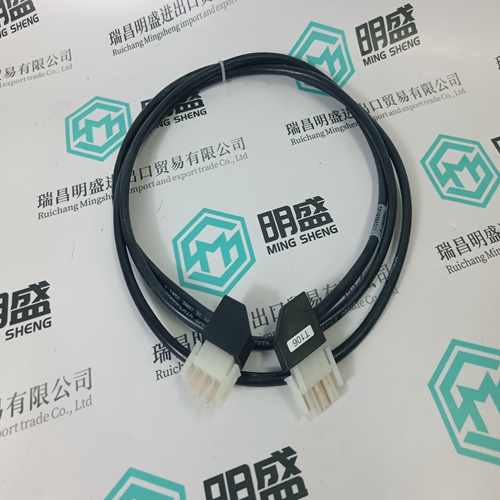
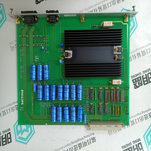
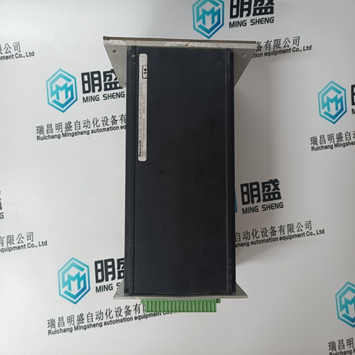
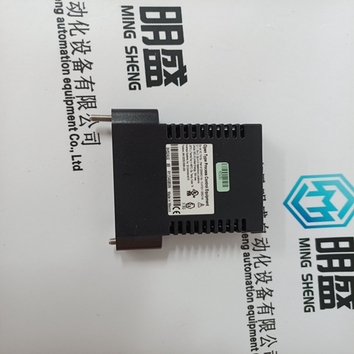
HONEYWELL 51401583-100 EPNI Digital card
- Product ID: 51401583-100 EPNI
- Brand: HONEYWELL
- Place of origin: The United States
- Goods status: new/used
- Delivery date: stock
- The quality assurance period: 365 days
- Phone/WhatsApp/WeChat:+86 15270269218
- Email:stodcdcs@gmail.com
- Tags:HONEYWELL51401583-100 EPNIDigital card
- Get the latest price:Click to consult
The main products
Spare parts spare parts, the DCS control system of PLC system and the robot system spare parts,
Brand advantage: Allen Bradley, BentlyNevada, ABB, Emerson Ovation, Honeywell DCS, Rockwell ICS Triplex, FOXBORO, Schneider PLC, GE Fanuc, Motorola, HIMA, TRICONEX, Prosoft etc. Various kinds of imported industrial parts
Products are widely used in metallurgy, petroleum, glass, aluminum manufacturing, petrochemical industry, coal mine, papermaking, printing, textile printing and dyeing, machinery, electronics, automobile manufacturing, tobacco, plastics machinery, electric power, water conservancy, water treatment/environmental protection, municipal engineering, boiler heating, energy, power transmission and distribution and so on.
HONEYWELL 51401583-100 EPNI Digital card
User connections are made to a standard screw terminal strip, and the rigid wiring system permits module insertion or removal without disturbing the wiring.Switch location and position The four position DIP-switch is located on the rear of the module. This switch controls the state of each channel when the system is reset or stopped. The output to the channel can either remain at the last value (Hold) or go to 0.0 mA Return-ToZero (RTZ). Set the switch for either hold or RTZ prior to installation of the module. Each of the four switches control the mode of operation for its associated output (i.e., switch 1 for output 1, etc.). Switch Settings The following figure presents DIP switch settings for the B872-100 module. Also, refer to the label located on the left side of the module itself.Set the switch to the left to select return-to-zero or to the right to select hold (viewing the rear of the module when held vertically). Channels are set independently. NOTE: The output state after power-up initialization is dependent on the position of DIP-switch. Open circuit in the following table results in current 0 mA.
Title of Overview Block
This test configures the module as follows: B872 (analog 4 channel output), and output state set to RTZ (return-to-zero). Required Parts Before starting, make sure you have the following items: z A loop power supply (24 Vdc, +/-10% at 1-2 A z A resistance decade box, or two 510 Ω resistors at 1/4 watts 5% z A AS-8535-000 high density connector The analog output module is calibrated at the factory prior to shipment. To ensure the module's accuracy you should calibrate the trim-pots for each output regularly. Calibration is recommended at 12 month intervals for operation between 25-45 ° C and at 6 month intervals between 0-60 ° C. Calibration Tools The following tools are needed to calibrate an analog output module: 1) A programming panel 2) A precision voltmeter, with an accuracy of +/-0.0001 volts on a 10 volt scale 3) A 1/4 inch Phillips screwdriver 4) A 1/8 inch standard screwdriver
Calibration Procedure (Method 1)
To make the adjustments, a load and loop supply must be connected to the channel being calibrated. There are two ways to make the adjustments. One procedure requires a load and loop supply to be assembled using voltage and resistance (Method 1). Refer to the calibration coltage/resistance procedure and the voltmeter connections diagram. The second procedure uses the existing field side circuit (Method 2). Refer to the calibration procedure, the voltmeter connections diagram, and the voltage/resistance chart. The following table the calibration voltage/resistance procedure (Method 1).Use a close tolerance 250 W resistor (+/-0.01%) and a voltage supply of between 12 and 35 Vdc. The voltage readings will be taken across the resistor. Connect as indicated in the upper part of the voltmeter connections diagram.Remove the two screws and the label located on the front panel of the analog output module. This allows you access to the trim-pots. There are two trim-pots per output. The first two trim-pots are for output number one, the second set is for output two, etc. Refer to the figure below for the location of trim pots.
