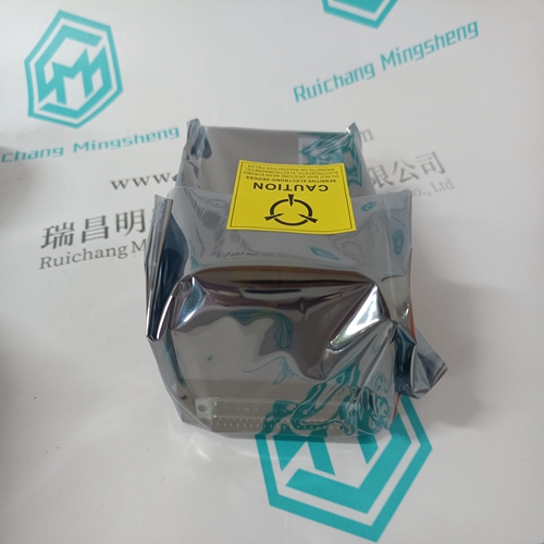
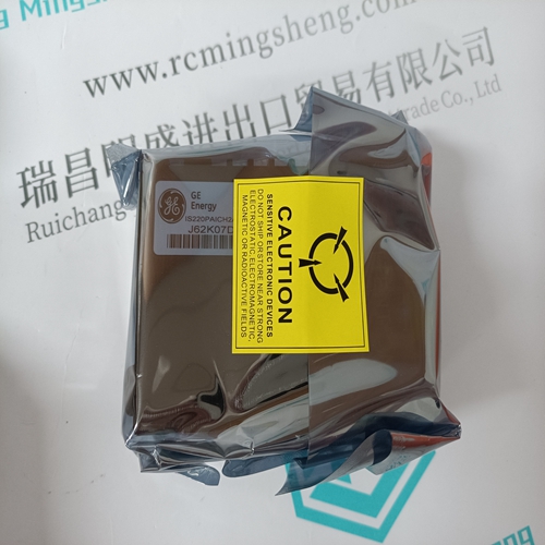
Home > Product > Gas turbine system > IS220PAICH2A 336A4940CSP11 General electric (ge) card
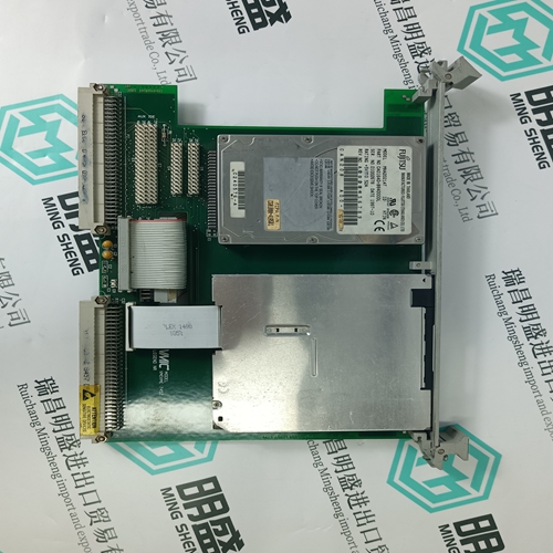
IS220PAICH2A 336A4940CSP11 General electric (ge) card
- Product ID: IS220PAICH2A 336A4940CSP11
- Brand: GE
- Place of origin: the United States
- Goods status: new/used
- Delivery date: stock
- The quality assurance period: 365 days
- Phone/WhatsApp/WeChat:+86 15270269218
- Email:stodcdcs@gmail.com
- Tags:IS220PAICH2A 336A4940CSP11General electric (ge) card
- Get the latest price:Click to consult
The main products
Spare parts spare parts, the DCS control system of PLC system and the robot system spare parts,
Brand advantage: Allen Bradley, BentlyNevada, ABB, Emerson Ovation, Honeywell DCS, Rockwell ICS Triplex, FOXBORO, Schneider PLC, GE Fanuc, Motorola, HIMA, TRICONEX, Prosoft etc. Various kinds of imported industrial parts
Products are widely used in metallurgy, petroleum, glass, aluminum manufacturing, petrochemical industry, coal mine, papermaking, printing, textile printing and dyeing, machinery, electronics, automobile manufacturing, tobacco, plastics machinery, electric power, water conservancy, water treatment/environmental protection, municipal engineering, boiler heating, energy, power transmission and distribution and so on.
IS220PAICH2A 336A4940CSP11 General electric (ge) card
If a user has a process where the over-range or under-range detection is immaterial, the unused voltage or current terminal, including the shields, on the field connector should be jumpered to case ground. If over-range or under-range detection is important to your process, and this detection is causing throughput problems with the unused channels (because they float or spike outside the range), then the unused voltage or current channels at the field connector, should be connected in parallel, to a valid Input channel. As long as the valid channel stays within range, the tied channels will also stay within range. For current, 4 to 20 ma operation, the valid Input is the only Input requiring the 250 Ω resistor to be in the circuit. Case ground is effective when the H8XX housing is connected to earth ground. The shield cannot be connected, both ends, to the device and the module. The exception to this is where the device shield is part of the device input circuit, and is not connected internally to device case ground. User Connections User connections are made to a standard screw terminal strip; and the rigid wiring system permits module insertion or removal without disturbing the wiring. B873-002 Terminal Numbering and Wire Connections B873-002 terminal numbering and corresponding input functions are presented below.
Update Interval Example
On an eight channel module, 2 channels are under range. All the registers assigned to the module will be updated every 1150 ms, until the inputs on the out of range channels return to the valid range. When they do, the update interval will return to 710 ms. Update Interval = (400 or 710) + (out of range channels X 220) Using the example above: (710) + (2 X 220) = 1150 ms If one channel returned to the valid range, the update interval would reduce to 930 ms. NOTE: As long as the channel is out of range, the register assigned to it will either have data of 0000 (4095 elevated), under range, or 4096 (8192 elevated), over range. (Refer to the data value reference chart) * The update interval is the amount of time necessary to update the data for all the registers assigned to the module.
Module Features
The B873-012 and B875-012 are analog input modules and can be used with 984 Programmable Controllers. The only difference between the two modules is that the B873-012 has four input channels and the B875-012 has eight input channels. Both modules accept inputs of -10 to +10 volt analog signals. The input is converted to a numerical value, ranging from 0001 to 8191. Values of 0000 or 8192 indicate invalid data. (Refer to the Data Value Reference Chart.) The value is directly proportional to the input signal. For example, an input voltage of -5V causes the module to send a value of 2048. If the input signal goes to 5 V, the module sends a value of 6144. (Refer to Input to Output Data Conversion Chart.) NOTE: 0.0 V or no voltage on an input channel produces a value of 4096. The PLC polls the module and places the values into input registers (30XXX) designated by the programmer. Each time the module is powered up, it performs diagnostic tests, resets the input latches, and, for each channel, presents a value of 0000 to the controller. The value is present for approximately three seconds after power up. The module will then start converting the inputs according to the schedule found in the Throughput Rate Section.
