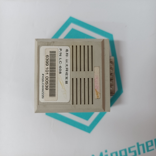
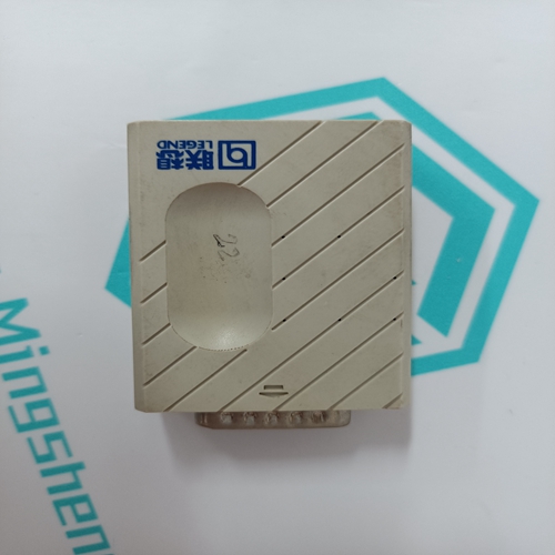
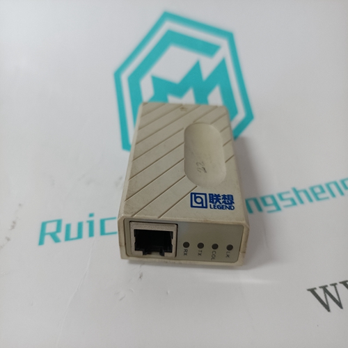
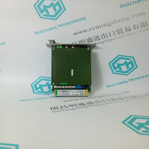
Home > Product > Robot control system > LENOVO LC-608 Ethernet transceiver
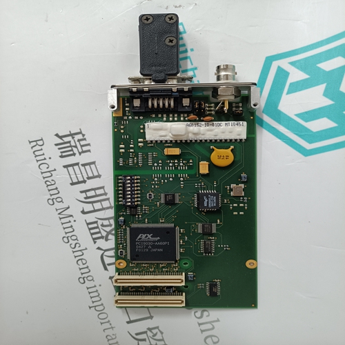
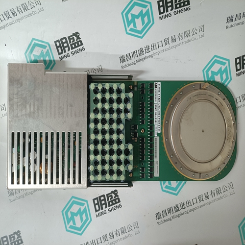
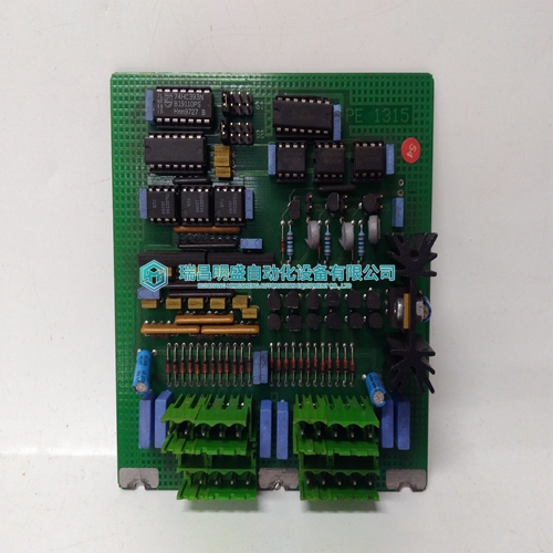
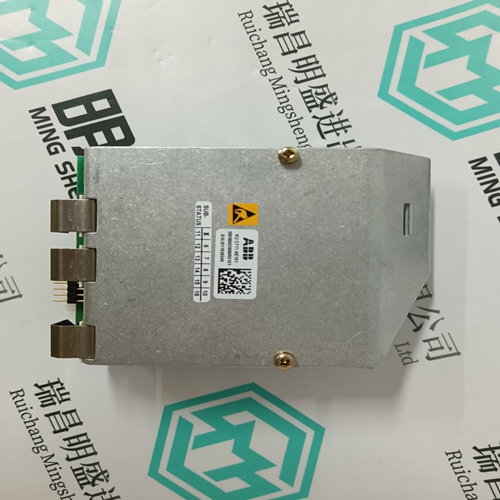
LENOVO LC-608 Ethernet transceiver
- Product ID: LC-608
- Brand: LENOVO
- Place of origin: CHINA
- Goods status: new/used
- Delivery date: stock
- The quality assurance period: 365 days
- Phone/WhatsApp/WeChat:+86 15270269218
- Email:stodcdcs@gmail.com
- Tags:LENOVOLC-608Ethernet transceiver
- Get the latest price:Click to consult
The main products
Spare parts spare parts, the DCS control system of PLC system and the robot system spare parts,
Brand advantage: Allen Bradley, BentlyNevada, ABB, Emerson Ovation, Honeywell DCS, Rockwell ICS Triplex, FOXBORO, Schneider PLC, GE Fanuc, Motorola, HIMA, TRICONEX, Prosoft etc. Various kinds of imported industrial parts
Products are widely used in metallurgy, petroleum, glass, aluminum manufacturing, petrochemical industry, coal mine, papermaking, printing, textile printing and dyeing, machinery, electronics, automobile manufacturing, tobacco, plastics machinery, electric power, water conservancy, water treatment/environmental protection, municipal engineering, boiler heating, energy, power transmission and distribution and so on.
LENOVO LC-608 Ethernet transceiver
The B882 module, with ability to sense its own output points is an excellent choice for critical operations. The example shown below shows ladder logic that allows for detection of point errors. This could ultimately be used to control a system if a critical failure occurred. The block move shown below moves the contents of registers30001 and 30002 into 40008 and 40009 where they can be worked. The XOR Block Exclusively OR’s the contents of 40001 and 40002 with 40008 and 40009, then places the results of this XOR in 40008 and40009. This gives a value that can be used in the compare block that compares the contents of 40001 and 40002 to the values in 40008 and 40009. When a miscompare occurs, coil 00001 turns on, which can be tied to an indicator light, or safety circuity for system protection. The following illustration provides an example of the application diagram The external power supply must provide power to the field side loads and the field side electronics. The amperage sizing requirements of this supply have three components: 160 mA/group maximum (all channels ON), plus steady state load current of all outputs capable of being ON simultaneously, plus the inrush current of all outputs capable of being switched simultaneously.
B882–116 24 Vdc Output
The B882–116 24 Vdc (16-point) output module monitors field points for both open and short circuit fault conditions. The module is designed for safety applications whereby it monitors essential field wiring. Two test modes are available: pulse test mode, and no pulse test mode. In no pulse test mode, the module detects open circuits only when the output point is off, and short circuits only when the point is on. Leakage current in the off state is less than 3 mA. Trip current to detect a short circuit is greater than 1 A. In pulse test mode, the module pulses the output to the opposite of the command state to determine the complete status of the output load. Pulse timing is: 500 s opposite state pulse once every second. NOTE: Average currents in output circuits are changed by no more than 0.1% by full test mode. Schematic diagram The following illustration is the B882–116 simplified schematic diagram
User connections are made to a standard screw terminal strip. The rigid wiring system permits module insertion or removal without disturbing the wiring. The following illustration shows the B882–116 terminal numbering and output connections
B882–116 24 Vdc Output, Configuration
This module appears as a B882 module when configured—i.e., the module requires either four 16-bit words—two 3x input registers and two 4x holding registers or 32 discrete 0x outputs and 32 discrete 1xinputs. The first holding register contains the command state programmed by the user. The input registers contains the faults detected. If an open circuit fault is detected on output point three, then a one is displayed in the 3x register at position three. If a short fault is detected on output point three, then a one is displayed in register 3x + 1 at position three. A one indicates a detected fault, whereas a zero indicates normal operation of that output point. The module uses only three of the four configured 16-bit words. A point that is shorted disables the output current flow. Once a fault is detected the operation follows the following flow chart if the module is in the pulse test mode of operation. If not in pulse test mode, then reported faults are cleared when a command changes it to the opposite state. In either case the detection of a short will force the point off. NOTE: The module will not work correctly with a J810 remote I/O processor. The B882–116 full fault test mode only flow chart is shown in the illustration below
