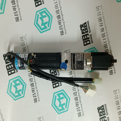
Home > Product > DCS control system > PM904F 3BDH001002R0001 Control module
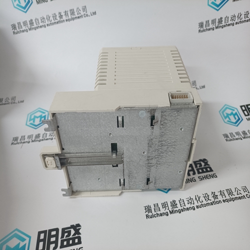
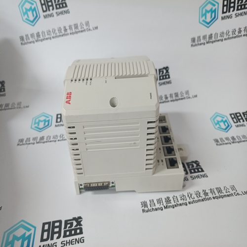
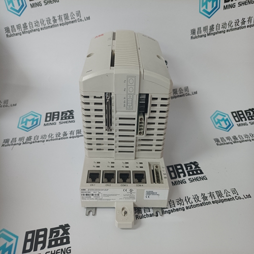
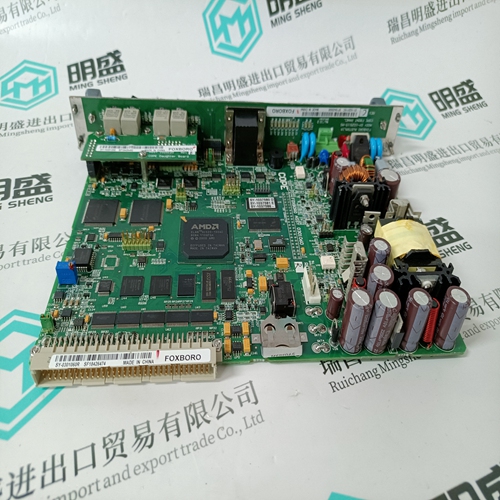
PM904F 3BDH001002R0001 Control module
- Product ID: PM904F 3BDH001002R0001
- Brand: ABB
- Place of origin: The Swiss
- Goods status: new/used
- Delivery date: stock
- The quality assurance period: 365 days
- Phone/WhatsApp/WeChat:+86 15270269218
- Email:stodcdcs@gmail.com
- Tags:PM904F 3BDH001002R0001Control module
- Get the latest price:Click to consult
The main products
Spare parts spare parts, the DCS control system of PLC system and the robot system spare parts,
Brand advantage: Allen Bradley, BentlyNevada, ABB, Emerson Ovation, Honeywell DCS, Rockwell ICS Triplex, FOXBORO, Schneider PLC, GE Fanuc, Motorola, HIMA, TRICONEX, Prosoft etc. Various kinds of imported industrial parts
Products are widely used in metallurgy, petroleum, glass, aluminum manufacturing, petrochemical industry, coal mine, papermaking, printing, textile printing and dyeing, machinery, electronics, automobile manufacturing, tobacco, plastics machinery, electric power, water conservancy, water treatment/environmental protection, municipal engineering, boiler heating, energy, power transmission and distribution and so on.
PM904F 3BDH001002R0001 Control module
A two-position dip switch located on the rear of the module is used to select one of two test modes on a group basis. No pulse test mode detects open circuits only when the output is off, and shorts circuits only when the point is on. Pulse test mode pulses the output to the opposite of the command state to determine the status of the output load. Each individual switch relate s to each group of eight output points. For example, DIP switch position #1 when set to on enables pulse test fault sensing for group 1(points 1-8). When a fault is detected the corresponding fault LED flashes independent of the test mode. When the switch is in the off position, no pulse test is performed. The pulse dip-switch settings for the B882–116 module is shown below.When using binary and BCD format, remember that output 16 is the LSB of word one and word two is ignored by the module.
The 24 V field supply must be rated to supply output load current +.5 A for the module, +5 A surge rating. This 5 A surge rating is required to correctly detect short circuits. Group input power fusing is recommended. The fuse should be rated for expected load current plus 5 A slo-blow.
B883–001 High Speed Counter
The B883-001 high speed counter module consists of two separate and independent counters and associated logic, and controls up to three outputs. After being configured, the module can operate independently of the PC and react to external events faster than the PC scan time. The module counters have the following characteristic: Counter #1 has bi-directional (up/down) count capability and has two inputs, two set points, a programmable maximum count, and two outputs. Counter 1 will also accept input from a quadrature type device such as an encoder. Counter #2 is an up counter and has one input, a programmable maximum count, and one output. Both counters accept pulsed inputs of 0 to 5, 0 to 12, or 0 to 24 Vdc at frequencies up to 50 KHz. the B883 options are selected by commands from the PC and by terminal wiring. Counter #1 has three modes of operation. Counter #2 can accept input either from an external source or from one of two internal clocks. Both counters can be configured to operate in a wide variety of applications (refer to the section on programming the B883)
Keying and Wiring
User connections are made to a standard screw terminal strip.The rigid wiring system permits module insertion or removal without disturbing the wiring. Terminal Numbering and Output Connections The following diagram shows terminal numbering and output connections for the the B883-001 module.
The B883-111 CAM module with velocity compensation and the B883-101 CAM module are 800 series input/output (I/O) modules with added microprocessor control capabilities. These modules are used to automate the operation of metal shaping power presses for any mass production industry such as motor vehicle manufacture and assembly. Both models of the CAM module are physically indistinguishable and will be discussed as a single unit. The CAM module receives a twelve-bit (plus control) parallel position code from an encoder. The module then transmits an eight-bit parallel control code to its discrete outputs based upon the received position data. Operating instructions in command form are loaded into the module from a programmable controller by way of the I/O system. After the commands are loaded, position codes received by the module are processed and outputted by the CAM module at a 4.000 Hertz rate. This speed is in excess of the PC’s scan rate. A total of 16 output intervals may be defined and distributed at random among eight outputs. CAM module inputs will be accepted in binary, binary coded decimal (BCD) or Gray code. If your application requires velocity compensation, choose the B883-111 module. The B883-111 module compensates for changes in velocity
