Home > Product > Gas turbine system > DS200TCQAG1BHF Gas turbine module
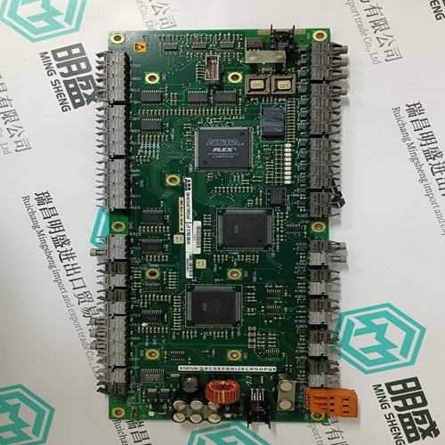
DS200TCQAG1BHF Gas turbine module
- Product ID: DS200TCQAG1BHF
- Brand: GE
- Place of origin: the United States
- Goods status: new/used
- Delivery date: stock
- The quality assurance period: 365 days
- Phone/WhatsApp/WeChat:+86 15270269218
- Email:stodcdcs@gmail.com
- Tags:DS200TCQAG1BHFGas turbine module
- Get the latest price:Click to consult
The main products
Spare parts spare parts, the DCS control system of PLC system and the robot system spare parts,
Brand advantage: Allen Bradley, BentlyNevada, ABB, Emerson Ovation, Honeywell DCS, Rockwell ICS Triplex, FOXBORO, Schneider PLC, GE Fanuc, Motorola, HIMA, TRICONEX, Prosoft etc. Various kinds of imported industrial parts
DS200TCQAG1BHF Gas turbine module
WARNING! Before installation, switch off the mains supply to the ACS 600. Wait five minutes to ensure that the intermediate circuit is discharged. Switch off all dangerous voltages connected to the inputs or the outputs of the ACS 600.ACS 600 Connection Ensure that the UDC+ and UDC– busses of the chopper are properly connected to the corresponding terminals of the ACS 600 (see Chapter 3 – Voltage Selection and Mechanical Installation). Resistor Cable Connection Connections at the braking resistor: (For terminal tightening torques, consult resistor documentation.) • Twist the screen wires together and connect them to the earthing terminal, along with conductor no. 3 (if present). • Crimp cable lugs of appropriate size onto conductors 1 and 2. • Connect conductor no. 1 to the R+ terminal. • Connect conductor no. 2 to the R– terminal. Connections at the braking chopper: Figure 4-7 Resistor cable stripping diagram (braking chopper end). All lengths are approximate and may vary according to the cable lugs used.
Electrical Installation
• Cut and strip the cable as shown in Figure 4-7 above. • Lead the cable through the cable entry into the converter unit. • Slip the copper sleeve (inserted into the earthing clamp at the factory) onto the outermost insulation of the cable so that insulation and sleeve edges are aligned (see Figure 4-6). • Bend the screen wires evenly backwards onto the copper sleeve. • Unfasten the screen earthing clamp and slip it onto the screen wires at the copper sleeve. Replace the clamp and tighten the fastening screw to 3 Nm. • Twist the screen wires together and connect to the earthing clamp on the chopper as shown in Figure 4-6. Tighten the screws to 3 Nm. • Connect conductor no. 3 (if present) to the earthing clamp on the chopper (below the screen earthing clamp) as shown in Figure 4-6. Tighten the screws to 3 Nm.• Crimp cable lugs onto conductors 1 and 2. (The screws on the R+ and R– busbars of the chopper are M8.) • Connect conductor no. 1 to the R+ terminal of the chopper. Support the back nut with a tool and tighten to 6 Nm. • Connect conductor no. 2 to the R– terminal of the chopper. Support the back nut with a tool and tighten to 6 Nm. • If a clamping cable gland is used at the cable entry, tighten it only after making the terminal connections.