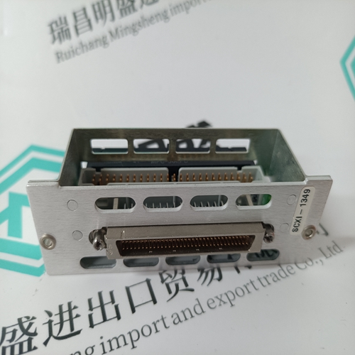
Home > Product > DCS control system > SK827005 SK827100-AS DCS coil
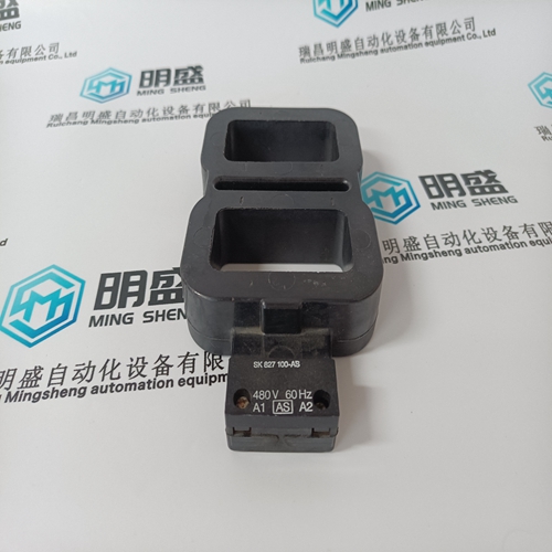
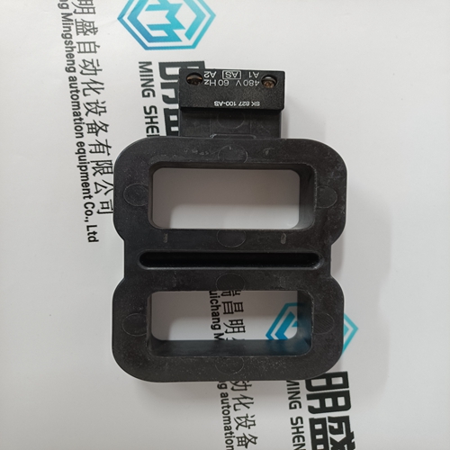
SK827005 SK827100-AS DCS coil
- Product ID: SK827005 SK827100-AS
- Brand: ABB
- Place of origin: The Swiss
- Goods status: new/used
- Delivery date: stock
- The quality assurance period: 365 days
- Phone/WhatsApp/WeChat:+86 15270269218
- Email:stodcdcs@gmail.com
- Tags:SK827005 SK827100-ASDCS coil
- Get the latest price:Click to consult
The main products
Spare parts spare parts, the DCS control system of PLC system and the robot system spare parts,
Brand advantage: Allen Bradley, BentlyNevada, ABB, Emerson Ovation, Honeywell DCS, Rockwell ICS Triplex, FOXBORO, Schneider PLC, GE Fanuc, Motorola, HIMA, TRICONEX, Prosoft etc. Various kinds of imported industrial parts
Products are widely used in metallurgy, petroleum, glass, aluminum manufacturing, petrochemical industry, coal mine, papermaking, printing, textile printing and dyeing, machinery, electronics, automobile manufacturing, tobacco, plastics machinery, electric power, water conservancy, water treatment/environmental protection, municipal engineering, boiler heating, energy, power transmission and distribution and so on.
SK827005 SK827100-AS DCS coil
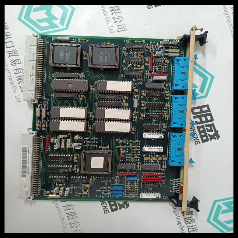
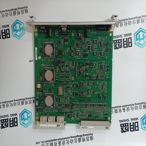
This board must be used together with a DCS 600 module equipped with a SDCS-CON-2 board including software S15.xxx. The board is equipped with an own controller with the following main functionalities: • The software structure implemented in this board is divided in two sections. The first section is built from the speed regulator and its additional functions which is producing the torque reference. • The second section is prepared to be programmed with its own characteristics for control and regulation. • Evaluation of the received data to produce a torque reference to be transmitted to the controller board CON-2. Actual values from the CON-2 are read, evaluated and retransmitted to the overriding control. Furthermore the board is equipped with three optical channels (max. data transmission speed is 4 Mb for each optical channel): - Channel 0 is used to communicate data from the overriding control (APC2 or via adapter modules from other controllers) to the DCS600-drive. - Channel 2 (Master-Follower) is used to operate two or more drives dependent on each other. Commands and values needed for this application are produced on this board. - Channel 3 is prepared to connect the PC tool for commissioning and maintenance.
DDCS Branching unit NDBU-95
DDCS Branching Unit (DBU) is used (only for DCS 600/DCF 600) to implement the star topology of DDCS link. This allows a slave unit to fail or become unpowered without disabling the communication. The NDBU receives messages from the master (PC) and sends them to all the slave units simultaneously. Each slave unit has an individual address and only the addressed slave unit sends a reply message to the master. It is also possible to use NDBU thus enabling peer-to-peer communication.
NDBU-95 DDCS Branching Unit has nine output channels where messages from the master are sent. The reply message sent by one slave unit is delivered to the master and it can be delivered also to other slaves if necessary. Several NDBU-95s can be used in parallel, in series or in any combination of these. The maximum distance between the master and NDBU-95 as well as between two NDBU-95s, see manual 3ADW000100R0201.
The AC share of the output DC voltage is measured with a capacitor and an auxiliary rectifier and used for current monitoring. Transistor relay is closed when the DC current is flowing (>0.02 A).
Field exciters
The DCS 500 system has different options for the field supply. There are one and three phase field exciters available, which can be either integrated (diode field exciter SDCS-FEX-1 and half controlled field exciter SDCS-FEX-2) or externally mounted (half controlled DCF503-0050 with the SDCS-FEX32 board and fully controlled DCF504-0050 with the SDCS-FEX-31 board). Three phase field exciters are converter modules themselves with the output current range similar to the DCS 501/601 or DCS 502/602. This possibility is described by a seperate documentation.
The Diode Field Exciter board SDCS-FEX-1 is a single phase diode rectifier for an AC input voltage up to 500 V and a DC output current of 6 A. The board has to be mounted inside the armature converter module. The excitation current is defined by the DC output voltage (line voltage multiplied by 0.9) and the resistance of the field winding. By using an external resistor in series with the field winding the field current can be adapted slightly. If the SDCS-FEX-1 board isn't already installed it must be mechanically fixed beside the electronic power part SDCS-POW-1 and connected via a flat cable to the SDCS-CON-x by using terminal X14.
