Home > Product > DCS control system > 1C31194G01 analog output module
1C31194G01 analog output module
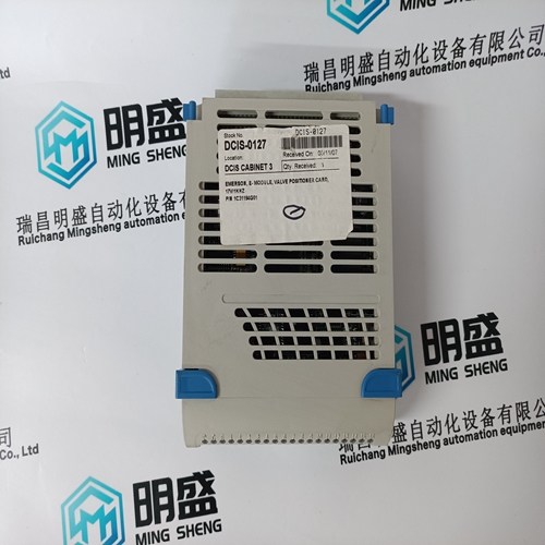
- Product ID: 1C31194G01
- Brand: EMERSON
- Place of origin: The United States
- Goods status: new/used
- Delivery date: stock
- The quality assurance period: 365 days
- Phone/WhatsApp/WeChat:+86 15270269218
- Email:stodcdcs@gmail.com
- Tags:1C31194G01analog output module
- Get the latest price:Click to consult
The main products
Spare parts spare parts, the DCS control system of PLC system and the robot system spare parts,
Brand advantage: Allen Bradley, BentlyNevada, ABB, Emerson Ovation, Honeywell DCS, Rockwell ICS Triplex, FOXBORO, Schneider PLC, GE Fanuc, Motorola, HIMA, TRICONEX, Prosoft etc. Various kinds of imported industrial parts
Products are widely used in metallurgy, petroleum, glass, aluminum manufacturing, petrochemical industry, coal mine, papermaking, printing, textile printing and dyeing, machinery, electronics, automobile manufacturing, tobacco, plastics machinery, electric power, water conservancy, water treatment/environmental protection, municipal engineering, boiler heating, energy, power transmission and distribution and so on.
1C31194G01 analog output module
If a DCF503A-0050 is in use two diode-thyristor modules are arranged as a half-controlled singlephase rectifier. If a DCS504A-0050 is in use four thyristor-thyristor modules are arranged as a fullcontrolled single-phase rectifier. The anodes of the two diodes (anodes / cathodes of the thyristors) are not connected directly to each other as usual; they are connected to the ends of the primary winding of the current transformer. The centre tap is the negative output of the rectifier. Thus it is possible to measure the DC current with an AC current transformer. A MOV (Metal Oxide Varistor) protects the AC input against voltage spikes from the external source. Another MOV protects the DC output against voltage surges which can be caused by the field winding of a DC machine. The free wheeling function needed e.g. during network failure is ”build in” because of the diodes, if the half-controlled version is in use. If the full-controlled version is used the free wheeling function is realized by using the thyristors in diode mode, triggered by a fast voltage rise.
Field exciter configurations
The data exchange between the SDCS-CON-x and the field exciter SDCS-FEX-2 or the DCF503A/ 504A-0050 is done via a RS485 serial link, which can be configured as a bus structure. This link is used to transfer references, actual values and settings for up to two field exciter units. The drive software located on the SDCS-CON-x board consists of two field supply functions, first field exciter and second field exciter. The first field exciter is already connected to the EMF controller to control the motor in all points of the motor diagram. The second field exciter is accessible via the field current reference. The RS485 interface works with a screened twowire cable. The allowed length is 5 m. The wires have to be connected to the terminals X2:1 and X2:2 and the screen to X2:3. Typical application of this kind is two DC motors connected to one converter. The load sharing can be done by means of adjusting the excitation current of the second DC-motor. There are two possible configurations for two Node numbers of the field exciters: - one SDCS-FEX-2 and one external field exciter (DCF503A-0050, DCF504A-0050 or 3-phase field exciter) or - two external field exciter units (DCF503A-0050, DCF504A-0050 or 3-phase field exciter).
Overvoltage Protection
If a SDCS-FEX-2 is used, it will be always recognized as the field exciter Node 1 by the software. If a DCF503A/504A-0050 is used as Node 1 or Node 2 it must be coded according to the table below. Node 2 is operating with a cycle time of 100 ms.Procedure for code changing of the DCF 503A/504A: • Switch off the units voltage supply • Set the appropriate switch according to the table • Initialization through switch on the electronics supply voltage The three-phase field supply converter DCF 501/502 and DCF 601/602 need a separate active Overvoltage Protection unit DCF 505 and DCF 506 for protection the power part against inadmissibly high voltages. The protection unit operates by switch on a freewheeling circuit between the F+ and F- connectors if a overvoltage occurs. The DCF 505/506 consists of a trigger unit and a free-wheeling thyristor (two in antiparallel at DCF 506). Thyristor firing is caused by a 1400 V (FEP1 - 500 V) and 1800 V (FEP2 - 690 V) trigger diode. The DCF 506 consist of a relay output for signalling the field supply converter that the overvoltage protection is active. The output is active in the free-wheeling process until the current is less than appr. 0.5 A.