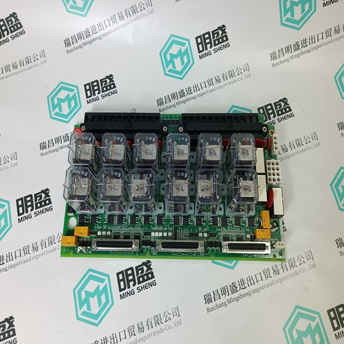
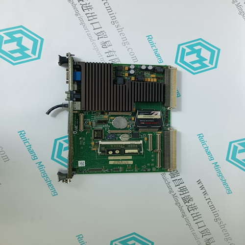
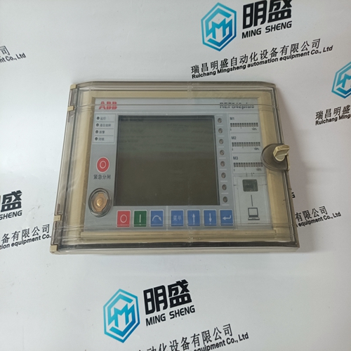
Home > Product > DCS control system > AIM0006 2RCA021397A0001F Sequential control card
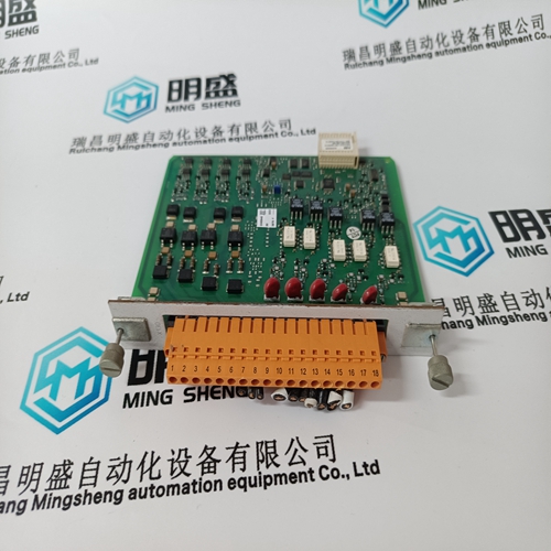
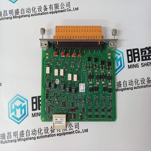
AIM0006 2RCA021397A0001F Sequential control card
- Product ID: AIM0006 2RCA021397A0001F
- Brand: ABB
- Place of origin: The Swiss
- Goods status: new/used
- Delivery date: stock
- The quality assurance period: 365 days
- Phone/WhatsApp/WeChat:+86 15270269218
- Email:stodcdcs@gmail.com
- Tags:AIM0006 2RCA021397A0001FSequential control card
- Get the latest price:Click to consult
The main products
Spare parts spare parts, the DCS control system of PLC system and the robot system spare parts,
Brand advantage: Allen Bradley, BentlyNevada, ABB, Emerson Ovation, Honeywell DCS, Rockwell ICS Triplex, FOXBORO, Schneider PLC, GE Fanuc, Motorola, HIMA, TRICONEX, Prosoft etc. Various kinds of imported industrial parts
Products are widely used in metallurgy, petroleum, glass, aluminum manufacturing, petrochemical industry, coal mine, papermaking, printing, textile printing and dyeing, machinery, electronics, automobile manufacturing, tobacco, plastics machinery, electric power, water conservancy, water treatment/environmental protection, municipal engineering, boiler heating, energy, power transmission and distribution and so on.
AIM0006 2RCA021397A0001F Sequential control card
Starting with revision 0C, RSR firmware supports a cascaded PI configuration in which the output of PI 1 is used as the target position input for PI 2. Additional features to support cascading operation are flags to select direct/indirect PI operation, and an anti-windup feature called “retreat”. Some of these new features are actually independent of cascading, but all are described in detail in this document.When full calibration is requested, the valve first travels to 0%. At 0%,demodulator gain is adjusted until the feedback voltage is near 10 volts. The demodulator gain at this point is the maximum possible demodulator gain. Then the valve travels to 100%. If the voltage is greater than 10 volts, or off-scale, demodulator gain is reduced, and a reading of the voltage is taken. This reading is the 100% calibration valve. Then the valve travels to 0% and a voltage reading is taken. This reading is the 0% calibration value. After the 0% calibration valve is determined, the new values are written to EE memory.
If the system is not properly tuned, the valve could start to go open when the servo output reaches the retreat value. If this occurs and ABS|Target-Feedback| > posErrorRetreat, a bit is set in register D to announce the condition. The RSR sends the output back to the rail and will not allow the channel to retreat again until seating is exited. The user should ensure that the bits in register D generate alarms to notify the operator should this occur.
SEATING, BACKSEATING, AND RETREAT
Seating and BackSeating are similar functions, with the exception that Seating closes the valve, and BackSeating opens it. Therefore, only Seating is described. Retreat is an anti-windup function. It is important to remember that when the RSR servo output is near 0 volts, the valve is stationary. When the servo output moves away from the midpoint, the valve moves to the desired position, and the servo output goes back to near 0 volts. Retreat is a feature that occurs after Seating. It is highly programmable. When the target position is less than seatLimit, the RSR goes into a seating mode. In this mode the RSR wants to close the valve as fast as possible. It accomplishes this by driving the output hard to the rail in the direction of valve closure. Retreat occurs after a timer has expired (retreatHoldT), and once the valve position is close to where the RSR wants it to be (ABS|Target-Feedback| < posErrorRetreat). When a valve retreats, the servo output goes from the rail to a programmed value (exitSeatVal) at a predefined rate (retreatRate).
In a typical scenario
the user would determine the voltage required to null the servo spool; i.e., overcome the mechanical bias adjustment. Let,s assume the value is –200 mV. The user would then set exitSeatVal to –200 mV plus an arbitrary amount in the direction of valve closure, 100 mV perhaps. So, the user would set exitSeatVal to –100 mV. Also, assume the user leaves the other associated constants to their default values. When seating is entered, the servo output goes to +10 volts and will remain there for at least 10 seconds. When the 10 second timer expires, and when position feedback is within 2 percent of the target position (probably 0), the servo output ramps from 10 volts to –100 mV at 10% per second. Ten volts is about 50% of output range, so the servo output would return to –100 mV after 5 seconds. At –100 mV, the servo spool is letting a small amount of fluid escape, thus closing the valve. If the target position went higher, thus removing the RSR from seating, the servo output would be readily available to begin to move the valve, and would not rely on integral action to bring it from 10 volts back to 0. When the RSR is moving between these various modes, the PI tracks the output when it is begin driven by one of the non-normal modes such as seating. Therefore, the transition back to normal operation is bumpless
