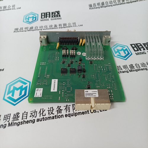
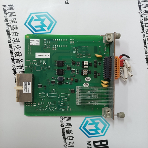
Home > Product > DCS control system > COM0003 2RAA005844A0006A Sequential control card
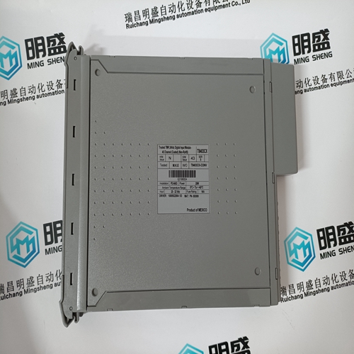
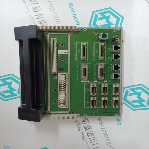
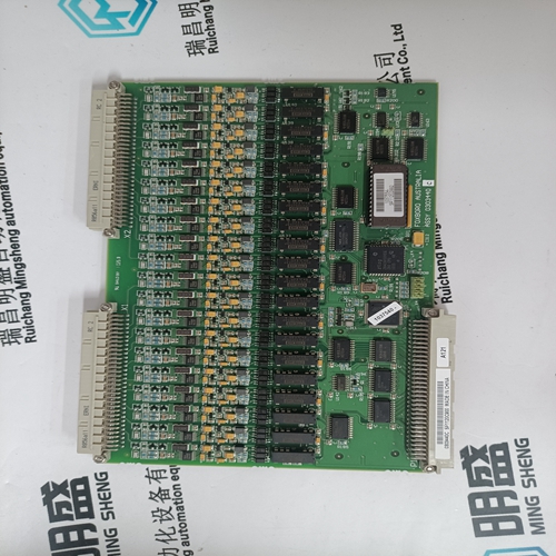
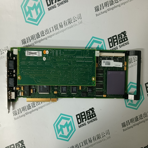
COM0003 2RAA005844A0006A Sequential control card
- Product ID: COM0003 2RAA005844A0006A
- Brand: ABB
- Place of origin: The Swiss
- Goods status: new/used
- Delivery date: stock
- The quality assurance period: 365 days
- Phone/WhatsApp/WeChat:+86 15270269218
- Email:stodcdcs@gmail.com
- Tags:COM0003 2RAA005844A0006ASequential control card
- Get the latest price:Click to consult
The main products
Spare parts spare parts, the DCS control system of PLC system and the robot system spare parts,
Brand advantage: Allen Bradley, BentlyNevada, ABB, Emerson Ovation, Honeywell DCS, Rockwell ICS Triplex, FOXBORO, Schneider PLC, GE Fanuc, Motorola, HIMA, TRICONEX, Prosoft etc. Various kinds of imported industrial parts
Products are widely used in metallurgy, petroleum, glass, aluminum manufacturing, petrochemical industry, coal mine, papermaking, printing, textile printing and dyeing, machinery, electronics, automobile manufacturing, tobacco, plastics machinery, electric power, water conservancy, water treatment/environmental protection, municipal engineering, boiler heating, energy, power transmission and distribution and so on.
COM0003 2RAA005844A0006A Sequential control card
Cascading of the PI controllers can be selected by entering “CASCADE = 1” and saving the setting by typing “SC”. When cascading is selected, the +100% to -100% output of PI 1 is converted to -100% to 0% target position. This target position value is then used as the target position, or demand,For VP firmware revisions 0H and later, the shutdown input is redefined to “Priority Demand Input”. When the input is activated, the target position is set to a tunable constant. For compatibility with previous firmware revisions, the default value of priorityDemand is -5%. This allows the user to rapidly move the valve to some intermediate position during upset conditions. The user has the flexibility to create his own scheme to handle an upset. While the “priority demand input”, or “Shutdown” input is active, the VP is in the local mode and the controller must unconditionally track demand feedback.For firmware revisions prior to 0F, the diagnostic works as described below. For later revisions servo coil voltage is measured and compared to a model described by tuning constants “kServo” and “kServoDb’. If the voltage does not fit into the model, due to being too large, “open coil” is blamed and the internal diagnostic bit is set. Then the timing sequence described below is used to post the error bit to the controller.
For firmware revisions prior to 0F
the diagnostic works as described below. For later revisions servo coil voltage is measured and compared to a model described by tuning constants “kServo” and “kServoDb”. If the voltage does not fit into the model, due to being too large, “open coil” is blamed and the internal diagnostic bit is set. Then the timing sequence described below is used to post the error bit to the controller.
For firmware revisions 0H and later, “priorityDemand” is the target position used when the shutdown input is activated. The default value is selected so that upgraded modules are backward compatible. The user can set this value to an intermediate value in order to create his own scheme for handling of plant upsets.
Simple calibration and checking of the system is carried out using push buttons on the Engineering Card fitted in each rack. More complex configuration can be carried out using the RS232 link between the Engineering Card and an external IBM compatible personal computer running the engineering interface software.
SYSTEM CONCEPT
In a system where the field wiring is required to be connected to the rear of the system, the rack is centrally divided into front and rear sections by a printed circuit board backplane which provides common signal routeing between individual Four Channel Control Cards. The control cards are fitted at the front of the rack while Quad Relay Interface Cards are fitted directly behind the associated Four Channel Control Card at the rear of the rack. The control cards and their respective interface cards are interconnected by a plug and socket arrangement. In a system where the field wiring is required to be connected to the front of a system, the Four Channel Control Cards and Quad Relay Interface Cards are mounted one above the other in a 6U rack. The backplane printed circuit board still provides the common signal routeing between the individual Four Channel Control Cards, but short cables at the rear of the cards connect each control card to their respective Quad Relay Interface Card.
